Evaluation of Interdental Spaces of the Mandibular Posterior Area for Orthodontic Mini-Implants with Cone-Beam Computed Tomography
Seyed Hossein Moslemzadeh1, Aydin Sohrabi2, Ali Rafighi3, Yusef Kananizadeh4, Amin Nourizadeh5
1 Assistant Professor, Department of Orthodontics, Tabriz University of Medical Sciences, Tabriz, East Azerbayjan, Iran.
2 Associate Professor, Department of Orthodontics, Tabriz University of Medical Sciences, Tabriz, East Azerbayjan, Iran.
3 Assistant Professor, Department of Orthodontics, Tabriz University of Medical Sciences, Tabriz, East Azerbayjan, Iran.
4 Postgraduate Student, Department of Oral and Maxillofacial Surgery, Tabriz University of Medical Sciences, Tabriz, East Azerbayjan, Iran.
5 Assistant Professor, Department of Prosthodontics, Tabriz University of Medical Sciences, Tabriz, East Azerbayjan, Iran.
NAME, ADDRESS, E-MAIL ID OF THE CORRESPONDING AUTHOR: Dr. Ali Rafighi, Assistant Professor, Department of Orthodontics, Golgasht Street, Azadi Ave., Tabriz-5165654186, East Azerbayjan, Iran.
E-mail: rafighi_ali@yahoo.com
Introduction
The use of mini-implants has increased in recent years because of their role in absolute anchorage, but the placement sites may affect the success or failure of the procedure, so it is very important to determine the appropriate and safe location for orthodontic mini-implants. On the other hand, the Cone Beam Computed Tomography (CBCT), which offers clear 3-Dimentional (3D) images, has been widely used in orthodontics and implant dentistry for surgical guidance of mini-implant placement.
Aim
The aim of this retrospective study was to evaluate inter-radicular spaces between mandibular canines to second molars using cone beam 3D images.
Materials and Methods
In this retrospective cross-sectional descriptive study, maxillofacial CBCT scan data were obtained from 40 adults. The 3D images were evaluated in five axial sections at 2, 4, 6, 8 and 10 mm from the cementoenamel Junction (CEJ). To determine inter-radicular spaces, tangent lines were drawn buccolingually to the roots in axial section and the minimum distance between these two lines was measured. The data was analysed using Friedman test with SPSS(ver.13).
Results
Interradicular spaces of canine to second molar increased from cervical to apical direction. The maximum distance was recorded at 4 mm from the CEJ between first and second molars.
Conclusion
According to our findings there is a distinct pattern of inter-radicular space changes in mandible. Attention to this pattern during placement of mini-implants can ensure the safety of the procedure.
Anchorage preparation, Temporary anchorage devices, Tooth movement
Introduction
Achieving maximum anchorage without any movement in the anchorage unit has always been one of the greatest challenges in orthodontics and the success of treatment generally depends on the anchorage preparations [1-3].
Conventionally, inclusion of more teeth in the anchorage unit or use of extraoral appliances to reinforce the anchorage unit has been a common practice [4,5].
However, after Kanomi R reported the use of orthodontic mini-implants for tooth movements in 1997, use of this technique increased significantly due to provision of a 100% anchorage, it’s easy insertion and removal and its reasonable cost [6]. Use of mini-implants makes it possible to move the teeth as desired and accurately, without any limitations [7-9]. It is very important to determine appropriate locations of mini-implants for successful results. Various criteria’s have been defined in this context, among which Nanda’s guidelines can be mentioned, including compatibility of mini-implant location with biomechanical design, avoiding damage to the anatomic structures, sufficient thickness of bone in the area and presence of adequate cortical bone for its stability [10].
Different studies have been carried out to standardize and customize these criteria with the use of different techniques to determine proper locations of the mini-implants. Most of the studies focused mainly on the surface characteristics, shape, form and primary stability of mini-implants, but limited numbers evaluated anatomic locations for safe placement of mini-implants in the maxilla and mandible [11-13]. Watanabe H et al., showed that root proximity was one of the factors that affected miniscrew failure especially in mandible [14], also the failure rate of mini-implants in the mandible has been reported to be higher than the maxilla [15,16]. In recent years, CBCT technique has been extensively used in orthodontics, implant dentistry, diagnosis of head and neck lesions and determining an exact location for the placement of mini-implants [17-21]. For evaluating the proximity of the mini-implants to the root, CBCT was superior to routine periapical radiographies [14]. The objective of this study was to evaluate inter-radicular spaces between canine and first premolar, first and second premolar, second premolar and first molar, and first and second molar teeth in the mandible using CBCT images.
Materials and Methods
This retrospective cross-sectional descriptive study was carried out in the Department of Orthodontics, Tabriz University of Medical Sciences, Iran. Sample size was calculated using Altman’s nomogram with consideration of alpha error of 0.05 and power of 80% [22], so 40 CBCT images (with 40 quadrants without tooth extraction) of a private Oral and Maxillofacial Radiology Center’s archive were taken from January to June 2011 and included in the study. Ethical clearance was obtained from Ethical Council of University for this study.
All CBCT images in which all teeth were present in each evaluated quadrant of the mandible except third molars, no orthodontic treatments before CBCT examination, and absence of any rotations and developmental malformations were included in the study.
The exclusion criteria included the CBCT with horizontal alveolar bone loss greater than 2 mm, crowding greater than 2 mm, spacing in the mandibular arch and women over 40 years of age.
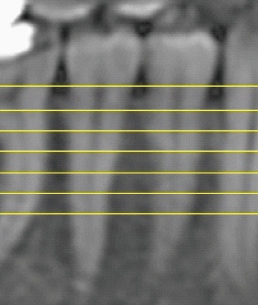
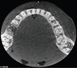
The 3D images were taken with CBCT apparatus (PlanmecaProMax, Finland) at 84 kVp, 2 mA and effective exposure time of six seconds and they were then evaluated with Planmeca Romexis Viewer 2.0.1 software by one oromaxillofacial radiologist. We took five axial cross-sections at 2, 4, 6, 8 and 10 mm from the CEJ in four areas: between canine-first premolar (3-4), first-second premolars (4-5), second premolar-first molar (5-6) and first-second molars (6-7). Each of these areas had individual reference lines between the CEJ of evaluated teeth and the cross-sections were relative to this individual line [Table/Fig-1]. To evaluate the inter-radicular spaces, two tangential lines were drawn to the mesial and distal surfaces of adjacent roots in the buccoingual direction, then the minimum distances between these two lines in each cross-section were measured using the ruler tool of the software [Table/Fig-2].
Coronal view with reference line drawn between the CEJ of the premolars and relative sections at 2,4,6,8,10 mm.
An axial view at 4 mm from the CEJ with the measurement of interradicular space between left first and second premolars of mandible with software’s ruler. (Images from left to right)
The inter-radicular spaces were measured in limits of roots from CEJ to apex. If alveolar bone resorption was more than 2 mm from CEJ or dental roots were shorter than 10 mm, the data was recorded as lost data. Since mini-implants should be placed in keratinized gingiva, and most of the teeth have the keratinized gingiva up to 4 mm from the CEJ [23], the inter-radicular spaces were compared at this cross-section to obtain an effective clinical approach.
Data were analysed using descriptive statistics of the measured inter-radicular spaces (means ± standard deviations) and normality test (Kolmogorov-Simonov). Then Friedman’s test was used to compare the mentioned spaces among five different cross-sections (2, 4, 6, 8 and 10 mm from the CEJ) in each area. The spaces of different areas (canine-first premolar, first-second premolar, second premolar-first molar and first-second molar) at 4 mm slice were compared with Friedman’s test too. When there was statistically significant, Wilcoxon signed rank test was used for pairwise comparison. All the analyses were carried out using SPSS 13. Statistical significance was set at p<0.05.
Results
Of 40 subjects included in this study, 11 (27.5%) were male and 29 (72.5%) were female. [Table/Fig-3] shows the descriptive data of four inter-radicular spaces at five cross-sections.
The results of descriptive statistics and estimation of the interradicular spaces at different areas in different cross-sections.
| Location* | Variable data | Lost data | Median | Mean | SD | Min | Max | 90% of subjects | 80% of subjects |
|---|
| 34.2 mm | 40 | 0 | 1.728 | 1.600 | 0.4624 | 0.8 | 2.9 | 1.200 | 1.400 |
| 34.4 mm | 40 | 0 | 1.937 | 1.900 | 0.5838 | 0.9 | 3.3 | 1.200 | 1.420 |
| 34.6 mm | 40 | 0 | 2.090 | 2.000 | 0.6488 | 0.9 | 3.6 | 1.310 | 1.600 |
| 34.8 mm | 40 | 0 | 2.375 | 2.350 | 0.7999 | 0.9 | 4.0 | 1.210 | 1.600 |
| 34.10 mm | 39 | 1 | 2.677 | 2.700 | 0.9178 | 0.9 | 4.7 | 1.600 | 1.800 |
| 45.2 mm | 40 | 0 | 2.493 | 2.400 | 0.6658 | 1.5 | 4.6 | 1.700 | 1.920 |
| 45.4 mm | 40 | 0 | 3.090 | 3.000 | 0.7837 | 1.3 | 4.9 | 2.210 | 2.500 |
| 45.6 mm | 40 | 0 | 3.510 | 3.450 | 0.9562 | 2.0 | 5.9 | 2.400 | 2.700 |
| 45.8 mm | 39 | 1 | 3.846 | 3.700 | 1.0541 | 2.1 | 6.4 | 2.400 | 3.100 |
| 45.10 mm | 39 | 1 | 4.400 | 4.200 | 1.1845 | 2.3 | 6.9 | 3.000 | 3.400 |
| 56.2 mm | 40 | 0 | 2.623 | 2.700 | 0.6395 | 1.2 | 3.8 | 1.700 | 2.100 |
| 56.4 mm | 40 | 0 | 2.923 | 2.950 | 0.7960 | 1.7 | 4.9 | 1.810 | 2.120 |
| 56.6 mm | 40 | 0 | 3.148 | 2.950 | 0.9476 | 1.5 | 5.9 | 2.030 | 2.520 |
| 56.8 mm | 40 | 0 | 3.850 | 3.800 | 1.1624 | 2.0 | 6.7 | 2.610 | 2.900 |
| 56.10 mm | 38 | 2 | 4.503 | 4.300 | 1.3826 | 2.3 | 8.1 | 2.700 | 3.180 |
| 67.2 mm | 40 | 0 | 3.050 | 2.850 | 0.7822 | 1.8 | 4.8 | 2.110 | 2.500 |
| 67.4 mm | 40 | 0 | 3.485 | 3.250 | 1.1913 | 1.6 | 7.1 | 2.300 | 2.420 |
| 67.6 mm | 40 | 0 | 4.020 | 3.750 | 1.5457 | 2.2 | 9.1 | 2.600 | 2.800 |
| 67.8 mm | 39 | 1 | 4.649 | 4.300 | 1.5765 | 2.3 | 8.5 | 2.900 | 3.200 |
| 67.10 mm | 35 | 5 | 5.337 | 5.300 | 1.8403 | 2.1 | 8.8 | 2.840 | 3.420 |
*Measurements have been expressed with abbreviations; for example, 34.2 mm, means interradicular distance between the canine and first premolar at 2 mm from the CEJ
Kolmogorov-Simonov test showed that all the data were not distributed normally. Therefore, non-parametric tests were used for data analysis. All inter-radicular spaces in each area showed significant differences at five slices as the results of Friedman and Post-hoc Wilcoxon signed rank tests, with a gradual increase in apical direction (p<0.001) [Table/Fig-4].
Comparison of five cross-sections in four inter-radicular areas (Friedman test and Post-hoc Wilcoxon signed rank tests).
| Location | 3-4 | 4-5 | 5-6 | 6-7 |
|---|
| 2 mm to CEJ | 1.600 | 2.400 | 2.700 | 2.850 |
| 4 mm to CEJ | 1.900a† | 3.000b | 2.950b | 3.250c |
| 6 mm to CEJ | 2.000 | 3.450 | 2.950 | 3.750 |
| 8 mm to CEJ | 2.350 | 3.700 | 3.800 | 4.300 |
| 10 mm to CEJ | 2.700 | 4.200 | 4.300 | 5.300 |
| p-value | <0.001 | <0.001 | <0.001 | <0.001 |
Locations have been expressed with abbreviations; for example, 3-4 mm, means
Interradicular distance between the canine and first premolar.
†: Same letters indicate statistical non-significant differences at p<0.001 level.
Friedman and Post-hoc Wilcoxon signed rank tests which were used to compare different areas at 4 mm cross-section showed significant differences in inter-radicular spaces between 3-4 and 4-5 and also between 5-6 and 6-7 (p<0.001, p=0.019 respectively). At 4 mm the greatest inter-radicular distance in all the cross-sections was between the first and second molars [Table/Fig-4].
Discussion
Appropriate anchorage preparation is one of the most important considerations in orthodontic treatments. Dental anchorage results in undesirable movement of the anchorage unit itself [24]. Therefore, if bone can be used as an anchorage unit, it would be possible to prevent unfavourable tooth movements, which was made possible after introduction of orthodontic mini-implants by Kanomi R in 1997 [6].
Several points should be considered when placing mini-implants, including the chemical composition, shape and size, avoiding damage to adjacent roots, and nerves and blood vessels. Further considerations are the presence of adequate bone between the roots and adequate cortical bone [25,26]. We have evaluated the cortical bone thickness of mandible for mini-implant placement using CBCT in a previous study and concluded that cortical bone thickness varies in different areas and increased from cervical to apical direction [27]. In the present study, the inter-radicular distances between the mandibular teeth were evaluated to place orthodontic mini-implants.
We found that the greatest inter-radicular distance in all the cross-sections was between the first and second molars; considering this area as the safest zone for the placement of orthodontic mini-implants in mandible. Hu KS et al., evaluated the relationship between dental roots and the surrounding tissues for the placement of mini-implants on dry skulls [12]. They also showed similar results as we found.
Poggio PM et al., reported that the greatest mesiodistal width of bone in the mandible is between the first and second molars; consistent with the results of our study [28].
Lee KJ et al., measured the distances between the dental roots at 4 and 8 mm cross-sections [29]. The inter-root distances increased progressively in apical direction at each cross section. These findings are in accordance with our results regardless of minor millimetric differences, but they did not compare the inter-radicular distances in different areas.
Lim JE et al., evaluated cortical bone thickness and inter-radicular distances between different teeth in the maxilla and mandible at 2, 4 and 6 mm from the alveolar crest and reported no significant differences in root proximity between men and women [30]. The minimum inter-radicular spaces were observed on the buccal aspect of both jaws between the two central incisors and central and lateral incisors. However, the maximum distance was reported for the buccal space between the second premolar and first molar, and other areas had values within those extremes. In the study of Lim JE et al., the measurements were relative to the alveolar crest which is not a reliable and stable reference point because it is affected by various factors such as periodontal diseases. We used the CEJ as a reference point for cross-sections because it does not change at all and provides proper visibility and access for the operator.
According to our findings the minimum and maximum interradicular distances were detected in 3-4 and 6-7 zones respectively; however, in the study of Lim JE et al the maximum distance was between 2nd premolar and 1st molar. Such differences may be attributed to inconsistency of the cross-sections and study designs [30].
In addition, we suggested a guideline to estimate inter-radicular distances in different areas and cross-sections at 80% and 90% confidence rates for clinical uses. The clinician can select appropriate mini-implant size based on estimated inter-radicular spaces at specific height relative to the CEJ of adjacent teeth.
In this study, we evaluated CBCT images of non-orthodontic samples without considering the age, and crowding less than 2 mm. Obviously both can affect the interradicular distances for mini-implant placement, so it would be better to design another study which include these parameters.
Conclusion
Within the limits of this study, the inter-radicular distances of the mandible increased gradually in apical direction from distal end of the canine to mesial end of the second molar. The maximum inter-radicular distance at 4 mm of the CEJ was recorded between the first and second molars.
*Measurements have been expressed with abbreviations; for example, 34.2 mm, means interradicular distance between the canine and first premolar at 2 mm from the CEJ
Locations have been expressed with abbreviations; for example, 3-4 mm, means
Interradicular distance between the canine and first premolar.
†: Same letters indicate statistical non-significant differences at p<0.001 level.
[1]. Kuroda S, Sugawara Y, Deguchi T, Kyung HM, Takano-Yamamoto T, Clinical use of mini-screw implants as orthodontic anchorage: Success rates and postoperative discomfortAm J Orthod Dentofacial Orthop 2007 131(1):9-15. [Google Scholar]
[2]. Miyawaki S, Koyama I, Inoue M, Mishima K, Sugahara T, Takano-Yamamoto T, Factors associated with the stability of titanium screws placed in the posterior region for orthodontic anchorageAm J Orthod Dentofacial Orthop 2003 124(4):373-78. [Google Scholar]
[3]. Cheng SJ, Tseng IY, Lee JJ, Kok SH, A prospective study of the risk factors associated with failure of mini-implants used for orthodontic anchorageInt J Oral Maxillofac Implants 2004 19(1):100-06. [Google Scholar]
[4]. Kim SH, Yoon HG, Choi YS, Hwang EH, Kook YA, Nelson G, Evaluation of interdental space of the maxillary posterior area for orthodontic mini-implants with cone-beam computed tomographyAm J Orthod Dentofacial Orthop 2009 135(5):635-41. [Google Scholar]
[5]. Agrawal N, Kallury A, Agrawal K, Nair PP, Alveolar bone exostoses subsequent to orthodontic implant placementBMJ Case Rep 2013 2013:piibcr2012007951 [Google Scholar]
[6]. Kanomi R, Mini-implant for orthodontic anchorageJ Clin Orthod 1997 31(11):763-77. [Google Scholar]
[7]. Wilmes B, Su YY, Drescher D, Insertion angle impact on primary stability of orthodontic mini-implantsAngle Orthod 2008 78(6):1065-70. [Google Scholar]
[8]. Asscherickx K, Vannet BV, Wehrbein H, Sabzevar MM, Root repair after injury from mini-screwClin Oral Implants Res 2005 16(5):575-78. [Google Scholar]
[9]. Song YY, Cha JY, Hwang CJ, Mechanical characteristics of various orthodontic mini-screws in relation to artificial cortical bone thicknessAngle Orthod 2007 77(6):979-85. [Google Scholar]
[10]. Erverdi N, Keles A, Nanda R, The use of skeletal anchorage in open bite treatment: A cephalometric evaluationAngle Orthod 2004 74(3):381-90. [Google Scholar]
[11]. Carrillo R, Rossouw PE, Franco PF, Opperman LA, Buschang PH, Intrusion of multiradicular teeth and related root resorption with mini-screw implant anchorage: A radiographic evaluationAm J Orthod Dentofacial Orthop 2007 132(5):647-55. [Google Scholar]
[12]. Hu KS, Kang MK, Kim TW, Kim KH, Kim HJ, Relationships between dental roots and surrounding tissues for orthodontic mini-screw installationAngle Orthod 2009 79(1):37-45. [Google Scholar]
[13]. Kang YG, Kim JY, Lee YJ, Chung KR, Park YG, Stability of mini-screws invading the dental roots and their impact on the paradental tissues in beaglesAngle Orthod 2009 79(2):248-55. [Google Scholar]
[14]. Watanabe H, Deguchi T, Hasegawa M, Ito M, Kim S, Takano-Yamamoto T, Orthodontic mini-screw failure rate and root proximity, insertion angle, bone contact length, and bone densityOrthod Craniofac Res 2013 16(1):44-55. [Google Scholar]
[15]. Hong SB, Kusnoto B, Kim EJ, BeGole EA, Hwang HS, Lim HJ, Prognostic factors associated with the success rates of posterior orthodontic mini-screw implants: A subgroup meta-analysisKorean J Orthod 2016 46(2):111-26. [Google Scholar]
[16]. Jing Z, Wu Y, Jiang W, Zhao L, Jing D, Zhang N, Factors affecting the clinical success rate of mini-screw implants for orthodontic treatmentInt J Oral Maxillofac Implants 2016 31(4):835-41. [Google Scholar]
[17]. Liang X, Jacobs R, Hassan B, Li L, Pauwels R, Corpas L, A comparative evaluation of Cone Beam Computed Tomography (CBCT) and Multi-Slice CT (MSCT) Part I. On subjective image qualityEur J Radiol 2010 75(2):265-69. [Google Scholar]
[18]. Ludlow JB, Davies-Ludlow LE, Brooks SL, Howerton WB, Dosimetry of 3 CBCT devices for oral and maxillofacial radiology: CB Mercuray, NewTom 3G and i-CATDentomaxillofac Radiol 2006 35(4):219-26. [Google Scholar]
[19]. Huang J, Bumann A, Mah J, Three-dimensional radiographic analysis in orthodonticsJ Clin Orthod 2005 39(7):421-28. [Google Scholar]
[20]. Wagner JD, Baack B, Brown GA, Kelly J, Rapid 3-dimensional prototyping for surgical repair of maxillofacial fractures: a technical noteJ Oral Maxillofac Surg 2004 62(7):898-901. [Google Scholar]
[21]. Hamada Y, Kondoh T, Noguchi K, Iino M, Isono H, Ishii H, Application of limited cone beam computed tomography to clinical assessment of alveolar bone grafting: A preliminary reportCleft Palate Craniofac J 2005 42(2):128-37. [Google Scholar]
[22]. Altman DG, Practical statistics for medical research 1990 CRC press [Google Scholar]
[23]. Mehta P, Lim LP, The width of the attached gingiva--much ado about nothing?J Dent 2010 38(7):517-25. [Google Scholar]
[24]. Cornelis MA, Scheffler NR, De Clerck HJ, Tulloch JF, Behets CN, Systematic review of the experimental use of temporary skeletal anchorage devices in orthodonticsAm J Orthod Dentofacial Orthop 2007 131(4 Suppl):S52-58. [Google Scholar]
[25]. Kang S, Lee SJ, Ahn SJ, Heo MS, Kim TW, Bone thickness of the palate for orthodontic mini-implant anchorage in adultsAm J Orthod Dentofacial Orthop 2007 131(4 Suppl):S74-81. [Google Scholar]
[26]. Baumgaertel S, Razavi MR, Hans MG, Mini-implant anchorage for the orthodontic practitionerAm J Orthod Dentofacial Orthop 2008 133(4):621-27. [Google Scholar]
[27]. Moslemzade SH, Kananizadeh Y, Nourizadeh A, Sohrabi A, Panjnoosh M, Shafiee E, Evaluation of cortical bone thickness of mandible with cone beam computed tomography for orthodontic mini implant installationAdvances in bioscience and clinical medicine 2014 2(2):9 [Google Scholar]
[28]. Poggio PM, Incorvati C, Velo S, Carano A, "Safe zones": A guide for mini-screw positioning in the maxillary and mandibular archAngle Orthod 2006 76(2):191-97. [Google Scholar]
[29]. Lee KJ, Joo E, Kim KD, Lee JS, Park YC, Yu HS, Computed tomographic analysis of tooth-bearing alveolar bone for orthodontic mini-screw placementAm J Orthod Dentofacial Orthop 2009 135(4):486-94. [Google Scholar]
[30]. Lim JE, Lee SJ, Kim YJ, Lim WH, Chun YS, Comparison of cortical bone thickness and root proximity at maxillary and mandibular interradicular sites for orthodontic mini-implant placementOrthod Craniofac Res 2009 12(4):299-304. [Google Scholar]