Iris Positioning Using a Grid Attached to a Spring Bow for a Custom Ocular Prosthesis
Ankita Chamaria1, Meena Ajay Aras2, Vidya Chitre3, Godwin Clovis Da Costa4
1 Postgraduate Student, Department of Prosthodontics, Goa Dental College and Hospital, Bambolim, Goa, India.
2 Professor and Head, Department of Prosthodontics, Goa Dental College and Hospital, Bambolim, Goa, India.
3 Professor, Department of Prosthodontics, Goa Dental College and Hospital, Bambolim, Goa, India.
4 Lecturer, Department of Prosthodontics, Goa Dental College and Hospital, Bambolim, Goa, India.
NAME, ADDRESS, E-MAIL ID OF THE CORRESPONDING AUTHOR: Dr. Ankita Chamaria, D/305, Suncity Complex. 105/1, Biddhan nagar road. Ultadanga, Kolkata-700067, India.
E-mail: ankita.chamaria12@gmail.com
Eyes are among the first features of the face to be noticed. Loss of an eye due to congenital, traumatic or pathologic aetiologies causes disfigurement and loss of sensory feedback. It leaves a psychological impact on the patient, thus prosthesis should be provided at the earliest to raise the spirits of the afflicted. Iris positioning is one of the important steps in fabricating customized ocular prosthesis. In facial asymmetry cases, comparison of both irises together can be a major disadvantage. This case report illustrates the use of a unique customized frame spring bow assembly to position the iris disk using the established parallelism between inter pupillary line to the horizontal plane.
Custom made, Post enucleation deficit, Stock ocular prosthesis
Case Report
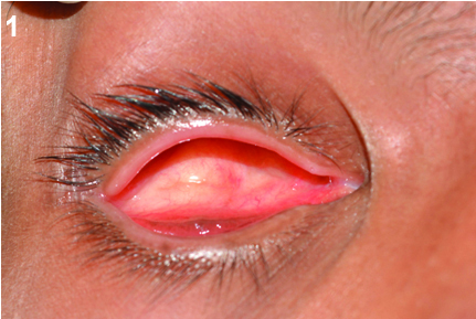
A 20-year-old male patient reported to the Department of Prosthodontics, with the chief complaint of missing right eye due to an automobile injury, 15 years ago. The patient was referred by the Department of Ophthalmology with the matching iris stock eye. On examination, the right eye socket exhibited eyelid constriction, reduced size and depth [Table/Fig-1]. A decision was made to fabricate a customized ocular prosthesis, using the iris from the stock eye.
Procedure
The patient was seated in an erect position to allow the tissues involved in the defect to be recorded in their natural drape. An impression of the orbital socket was made with light body addition silicone impression material (Aquasil, DENTSPLY) using a special tray fabricated from the stock eye [Table/Fig-2a,b].
a) Tray with mixing tip; b) Impression with light body; c) Putty index; d) Wax conformer.
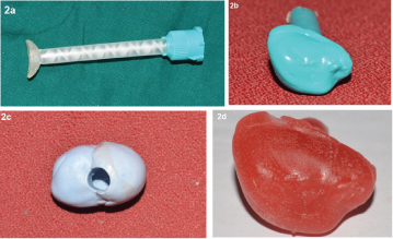
The impression was immersed in putty addition silicone impression material (Aquasil, DENTSPLY) to obtain an index [Table/Fig-2c]. A wax conformer was fabricated by flowing molten wax (Modelling Wax, Deepti Dental Products of India Pvt. Ltd.) in the index [Table/Fig-2d], tried in the patient’s eye socket and adjusted for desired volume, retention and comfort.
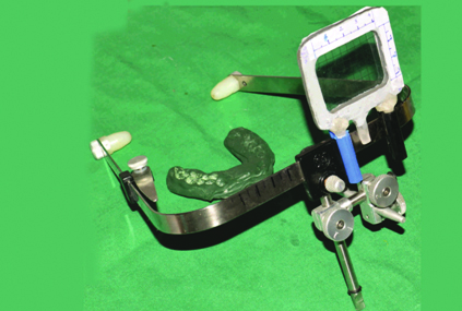
A special assembly which consisted of a heat cured acrylic resin (DPI, Mumbai) frame with a graph grid, attached to a Hanau spring bow was used to position the iris accurately [Table/Fig-3]. The frame was made with equal lines of graph grid on either side of the midline of the scale. The innate markings on the graph grid and a scribed scale on the spring bow helped in accurate positioning of the frame on the spring bow. The scale was attached to the spring bow using ball point pen caps.
Graph grid frame attached to spring bow.
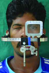
The patient was placed in the aesthetic reference position and an outline of the iris of the left eye was traced on the graph grid [Table/Fig-4].
Iris outline of left eye.
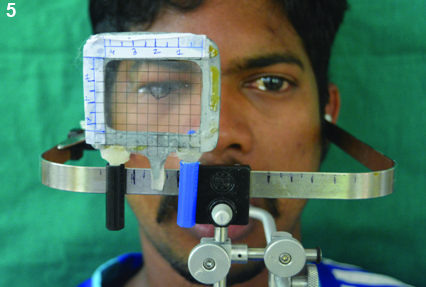
The markings were transferred to the wax conformer by flipping the graph grid on the right side of the patient using the markings on the spring bow to maintain symmetrical distance on either side. The iris disk from the stock eye was cut according to the measured dimensions and placed on the markings [Table/Fig-5].
Transfer of markings on right eye.
The wax conformer with the stock iris was tried in. After the final adjustments and ascertaining the patient’s satisfaction, the wax conformer was processed in the conventional manner.
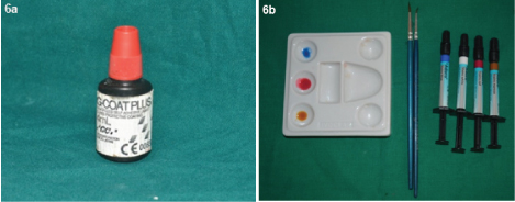
The prosthesis was characterized using Adoro stains [Table/Fig-6a] and cured in the curing unit. The stains were protected using the protective coating (G-Coat Plus, GC America Inc.) [Table/Fig-6b].
a) Adoro stains; b) G Coat Plus.
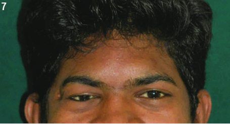
The prosthesis was delivered to the patient with post delivery instructions. He was advised to limit the removal of the prosthesis to once in a day for cleaning. The cleaning can be done by hand washing with soap and water. Recall visit was advised annually for polishing to prevent deposition of proteins and bacteria. The patient was happy and satisfied with the prosthesis [Table/Fig-7].
Patient with the prosthesis.
Discussion
Congenital defects, accidental trauma or pathologies may lead to surgical intervention, hence resulting in removal of eyeball [1]. Defects of the eye can be classified as ocular or orbital. Ocular defects show the involvement only of eyeball whereas orbital defects include periorbital tissue as well [2]. Peyman GA et al., has classified surgical procedures adopted for eye removal into three categories: Evisceration (removal of the eye with sclera intact), Enucleation (removal of the entire eye including globe with orbital contents in place) and extenteration (removal of the contents of the eye socket including the muscles, lacrimal glands, optic nerve) [3]. For the former two procedures, ocular prosthesis is fabricated and for latter, orbital prosthesis is given. Ocular prosthesis can be either prefabricated stock eyes or custom-made [4]. Custom-made ocular prosthesis achieves intimate contact with the tissue bed enabling ideal fit and distributes pressure equally on the tissue bed [5]. The procedures for a custom-made ocular prosthesis include impression of the socket, wax pattern trial, iris positioning and acrylization.
The positioning of iris is an important step in the fabrication of custom-made ocular prosthesis.
Bilateral symmetry is as crucial in iris positioning as it is in dental restorations. For rehabilitating teeth, interpupillary line and horizontal plane are used as a reference line along with a facebow. Horizontal plane is captured by positioning the patient in Natural Head Position (NHP/also called as aesthetic reference position/ERP). NHP is the position of the head most comfortable for a patient gazing at the horizon [6]. The facebow records the orientation of the maxilla while patient sits upright with arms of facebow parallel to horizontal plane and interpupillary line. Keeping the same principle in mind, an innovative technique is devised for rehabilitating eye defects wherein facebow is aligned parallel to horizontal reference plane and customized scale along with graph grid helps in accurate transfer of iris position (by obtaining interpupillary line). The technique described derives advantages of various methods advised previously i.e. using customized scale [7] and graph grid [8], hence ensuring bilateral symmetrical iris positioning along with interpupillary line.
Other advantages of this technique are it is less time consuming, requires minimal skill, no need for assistance, uses established reference plane, allows repeated checking of iris position, can be used for multiple patients and is easy to use in clinical setup. The disadvantage is the limitation in the selection of colour and size of the iris. Various methods proposed for iris positioning along with their disadvantages have been tabulated in [Table/Fig-8] [8–14].
Summary of the methods used for iris positioning.
| Techniques for iris positioning | Subjective perception | Infeasibility in clinical set-up | Errors in facial asymmetry |
|---|
| Graph grid [8], mounted graph grid [9] | | | ✔ |
| Standard measurements from midline to pupil [10] | | | ✔ |
| Iris positioning devices like pupillometer [11], ocular locator [12], customized 3-D scale [7] | ✔ | ✔ | |
| Others- visual judgement [13], light reflection [14] | ✔ | | |
Conclusion
Symmetry is important for the aesthetic appearance of the maxillofacial prosthesis, with ocular and orbital prosthesis being no exception. Accurate orientation of iris disk assembly largely contributes to the success of ocular and orbital prosthesis. The technique described in the article uses the established reference plane which hence gives an accurate registration of position of iris disk assembly.
Declaration of patient consent: The authors certify that they have obtained appropriate consent form. In the form the patient has given his consent for his images and other relevant clinical information to be reported in the journal.
[1]. Raflo GT, Enucleation and evisceration. In: Tasman W, Jaeger E (eds)Duane’s Clinical Ophthalmology 1995 vol 5ed 2Philadelphia, PALippincott:1-25. [Google Scholar]
[2]. Babu AS, Manju V, Nair VP, Thomas CT, Prosthetic rehabilitation of surgically treated orbital defects-Evisceration, enucleation, and exenteration: A case seriesJ Indian Prosthodont Soc 2016 16(2):216 [Google Scholar]
[3]. Peyman GA, Sanders DR, Goldberg MF, Principles and practice of ophthalmology 1987 Vol.31st Indian edNew DelhiJaypee Bros:2 [Google Scholar]
[4]. Raizada K, Rani D, Ocular prosthesisContact Lens and Anterior Eye 2007 30(3):152-62. [Google Scholar]
[5]. Ow KKR, Amrith S, Ocular prosthetics: Use of a tissue conditioner material to modify a stock ocular prosthesisJ Prosthet Dent 1997 78:218-22. [Google Scholar]
[6]. Chitre V, Need for an anterior point of reference in face bow transfer: The changing viewpoint. Changing concepts regarding anterior reference pointJ Indian Prosthodont Soc 2006 6:112-14. [Google Scholar]
[7]. Gupta L, Aparna IN, Dhanasekar B, Prabhu N, Malla N, Agarwal P, Three-dimensional orientation of iris in an ocular prosthesis using a customized scaleJ Prosthodont 2014 23:252-55. [Google Scholar]
[8]. Guttal SS, Patil NP, Vernekar N, Porwal A, A simple method of positioning the iris disk on a custom-made ocular prosthesis. A clinical reportJ Prosthodont 2008 17:223-27. [Google Scholar]
[9]. Pai UY, Ansari NA, Gandage DS, A technique to achieve predictable iris positioning and symmetry in ocular and orbital prosthesesJ Prosthodont 2011 20:244-46. [Google Scholar]
[10]. Prasad K, Prasad A, Alva H, Fabrication of customised aesthetic acrylic ocular prosthesisGuident 2013 6(8):10 [Google Scholar]
[11]. Roberts AC, An instrument to achieve pupil alignment in eye prosthesisJ Prosthet Dent 1969 22:487-89. [Google Scholar]
[12]. McArthur RD, Aids for positioning prosthetic eyes in orbital prosthesisJ Prosthet Dent 1977 37:320-26. [Google Scholar]
[13]. Benson P, The fitting and fabrication of a custom resin artificial eyeJ Prosthet Dent 1977 38:532-38. [Google Scholar]
[14]. Joneja OP, Madan SK, Mehra MD, Dogra RN, Orbital prosthesesJ Prosthet Dent 1976 36:306-11. [Google Scholar]