Anchorage control with minimum unwanted side effects is a pre-requisite and a critical factor in determining the success of orthodontic treatment. The increasing demand for orthodontic treatment methods requiring minimal compliance and maximal anchorage control has led to exploration of “bone supported anchorage” or skeletal anchorage. The important advantage of orthodontic mini-implant is its non-invasive placement procedure and ease of retrieval after the treatment [1,2]. The time lag between loading and placement is shortened reducing the treatment period and thus, increasing patient acceptability [3,4]. Primary stability or the initial stability is an important factor for mini-implant success [1,2]. The resistance to an orthodontic loading force ranging between 30g and 250g used in different orthodontic movements is mainly provided by primary stability [5,6]. The short wait hold period is sufficient for healing but not for osseointegration, which is an important factor in maintaining a rigid anchorage unit. There are controversial reports cited in the literature regarding the time lag interval of loading these mini-implants. According to Miyawaki S, Melsen B and Costa A, Roberts WE and Saito S et al., time lag for bone healing and osseointegration before orthodontic loading is not necessary because the primary stability of the mini-screws is sufficient to withstand the regular orthodontic loading and the orthodontic forces can be applied immediately [1,6–9]. However, in contrast the studies done by Liou EJW and Cheng SJ concluded that a waiting period of a minimum of 15 days is warranted before the orthodontic loading [2,3]. In case of orthodontic mini-implants in the mandible, Kanomi suggested a period of healing and osseointegration before a screw inserted in the mandible is loaded [10]. According to Becker W et al., and Schnitman PA et al., too early loading is associated with an increased failure rate [11,12]. On the other hand Garg KK concludes that waiting period between mini-screw placement and orthodontic loading does not significantly affect the mini-screw mobility so immediate loading can be recommended [13].
The behaviour of mini-screws under orthodontic loading is not clearly established from the available studies. Therefore, the aim of the present study was to directly determine and compare the reciprocal displacement of orthodontic mini-implant under two types of loading protocols during orthodontic retraction. According to null hypothesis no significant differences were noted in the displacement pattern of implant, molars and anterior teeth irrespective of the type of loading.
Materials and Methods
This prospective clinical study was done as a part of the treatment procedure for the patients registered for orthodontic treatment at Narayana Dental College, Nellore, Andhra Pradesh, India, between January 2015 to October 2015. A split mouth technique was utilized with immediate loading on one side and delayed loading on the other side. Stratified randomization between right and left sides was done to prevent the allocation bias. In the study to ensure that the power of the test is 80% to detect a difference of 1mm between left and right sides, a two sided test was used with a 5% level of significance and the minimum sample size was estimated to be 14 each side. However, a sample of 25 patients (Females:15; Males:10) was drawn for this study. The inclusion criteria included the patients with good physical and mental health in the age range of 18-25 years, average growth pattern of 25-30° of Frankfort-Mandibular Plane Angle (FMA), Angle’s Class I bimaxillary protrusion case, Type-A anchorage cases with extraction of first premolar in all the quadrants and with anterior crowding below 2-3mm [Table/Fig-1]. The exclusion criteria included the patients who were on drug therapy that may directly or indirectly affect the Orthodontic Tooth Movement (OTM), those with abnormal vertical and horizontal growth pattern. All non-extraction cases and extraction cases with Type B and Type C anchorage were excluded from the study. The informed consent was taken from each individual separately. Ethical committee clearance has been obtained from the institution (Letter No: D138408008, Date: 27.03.2014).
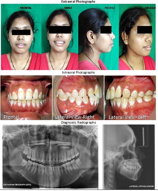
Pre-treatment diagnostic records.
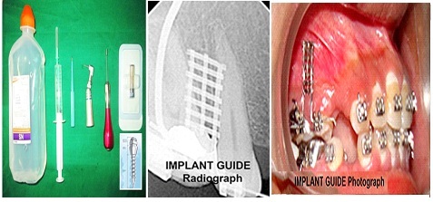
All the cases were planned to be treated by standard MBT technique (Masters Series of 0.022 Slot, American Orthodontics, Sheboygan, Wis) with sliding mechanics. The cases were fitted with Transpalatal Arch (TPA arch) in the maxillary arch and lingual arch in the mandibular segment. Initial aligning with 0.16" Nitinol, 0.16 X 0.22" Nitinol and 0.17X 0.22" Nitinol wires was achieved with in 2-3 months. The mini-screws TomasTM pin SD 08 (Dentaurum, Ispringen, Germany) with 1.2mm diameter of width and 8mm in length were used for retraction [Table/Fig-2]. The implant was placed between the maxillary 1st permanent molar and 2nd premolar using implant guide [Table/Fig-2] [14]. The appropriate height of 8mm was measured by taking the Intraoral Periapical (IOPA) radiograph after the guide placement. The mini-screw was inserted to a depth of 4mm under local anesthesia. A five days course of antibiotics and 2% chlorhexidine mouth rinse were prescribed, and the patients were instructed to maintain oral hygiene.
Armamentarium used during implant placement.
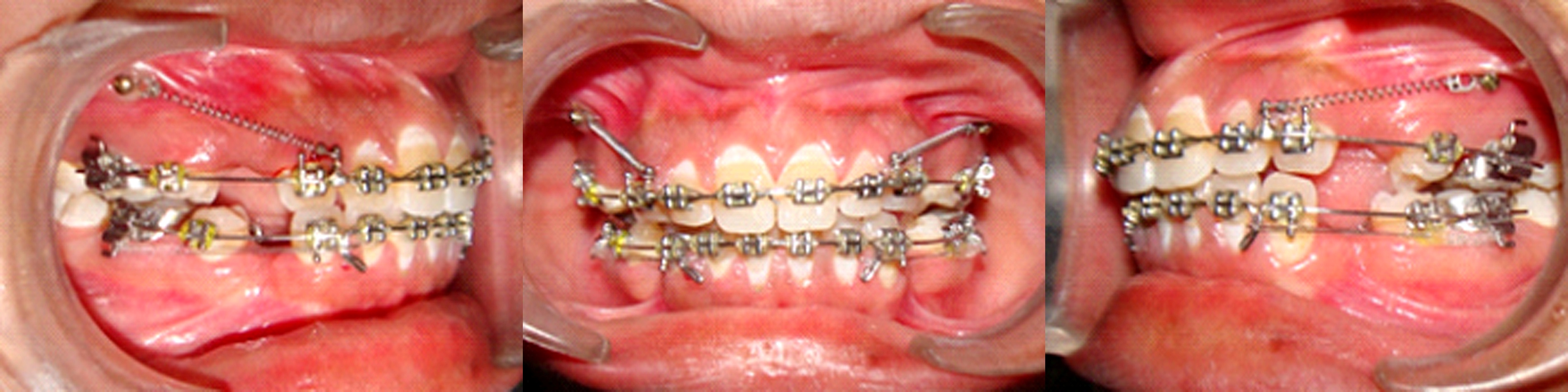
The site of each patient with immediate loading was designated as ‘R’ and that on opposite side designated as ‘L’ and loading was done after an initial delay of two weeks. Enmasse anterior retraction on 0.019 X 0.025” stainless steel base arch wire with a closed coil NiTi spring (Prime Orthodontics, India) exerting 150g of force as measured by Dontrix gauge [Table/Fig-3]. In the mandibular arch elastic modules generating 90g of force was used for retraction.
Implants loaded with retraction NiTi coil springs.
Calibration of the Orthopantomograph: The Digital Orthopanto-mograph (OPG) (Promax, Model 2008, Planmeca, Helsiniki, Finland) with standard exposure parameters (66kV, 9.8mv, 15.8s) were utilized for calibration of measurements. The OPGs were taken at two different points of time with ‘T1’ taken immediately after loading the implant and ‘T2’ was the point of time after three months of loading. Certain landmarks and reference lines were defined and utilized in the study and measurements with prefix ‘R-’ and ‘L-’ indicates measurements on immediate and delayed side respectively.
Landmarks [Table/Fig-4]:
The landmarks identified in the study.
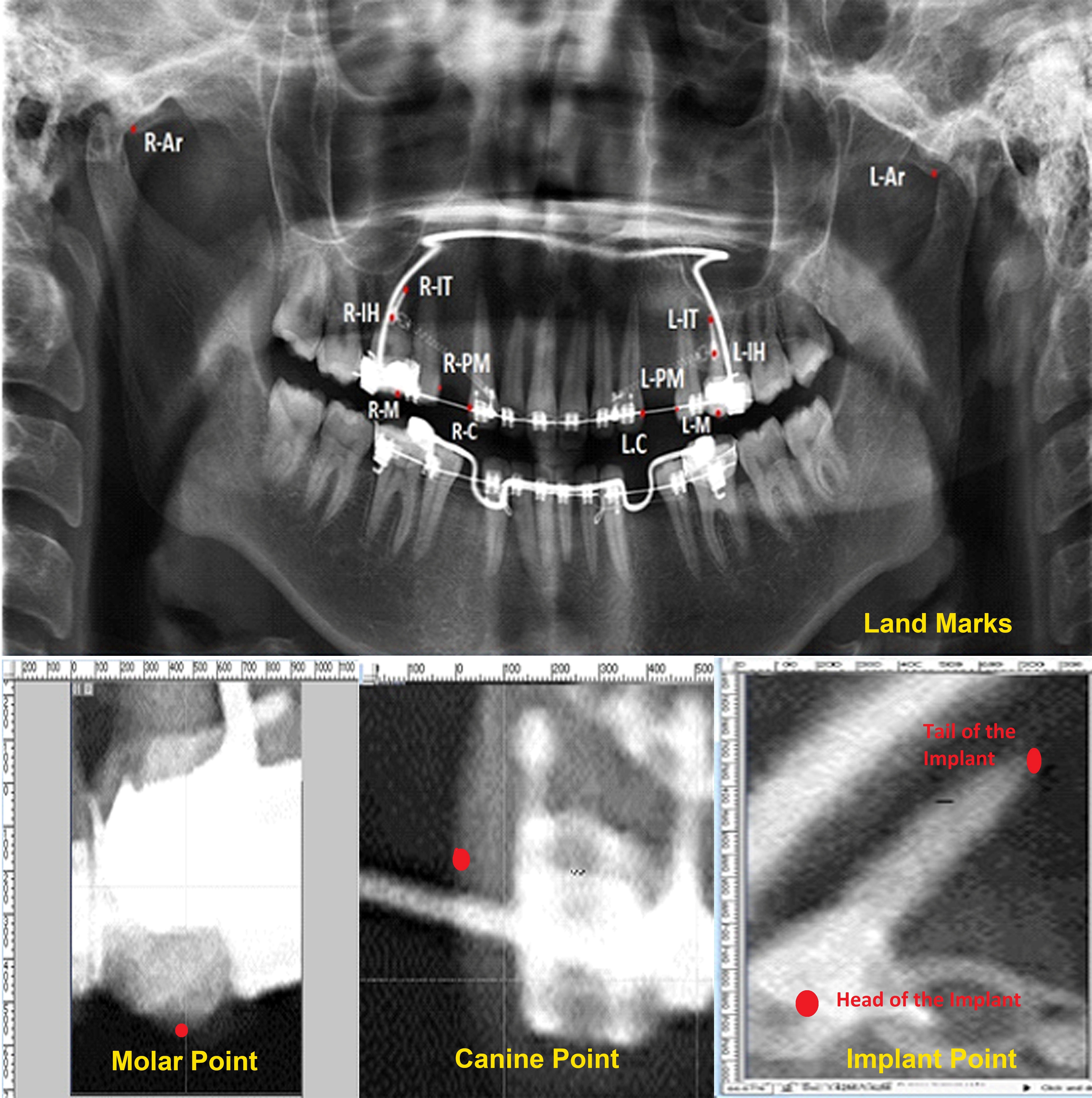
Articulare (Ar): The lowest vertical point of the articular eminence.
Head of the Implant (IH): The centre point of the head of implant.
Tail of the Implant (IT): The most apical tip of the screw of implant.
Molar point (M): The mesiobuccal cusp tip of the first molar.
Canine point (C): The distal most point in the distal curvature of the maxillary canine.
Premolar point (PM): The distal most point in the mesial curvature of the maxillary premolar.
Reference lines [Table/Fig-5], articulare plane or the horizontal reference plane is the line joining the right and left articulare points. (‘R- Ar’ to ‘L-Ar’). A mid point bisector is constructed on this plane and a perpendicular passing through this point is chosen as a vertical plane of reference of “Y-axis”. All the horizontal distances were measured with reference to this vertical axis and parallel to the articular plane. Two more vertical planes were constructed passing through the tangents of the point ‘C’ and ‘PM’. The horizontal space measured between them gives the amount of extraction space remaining. The distances measured are given below:
Reference planes and measurements used in the study.
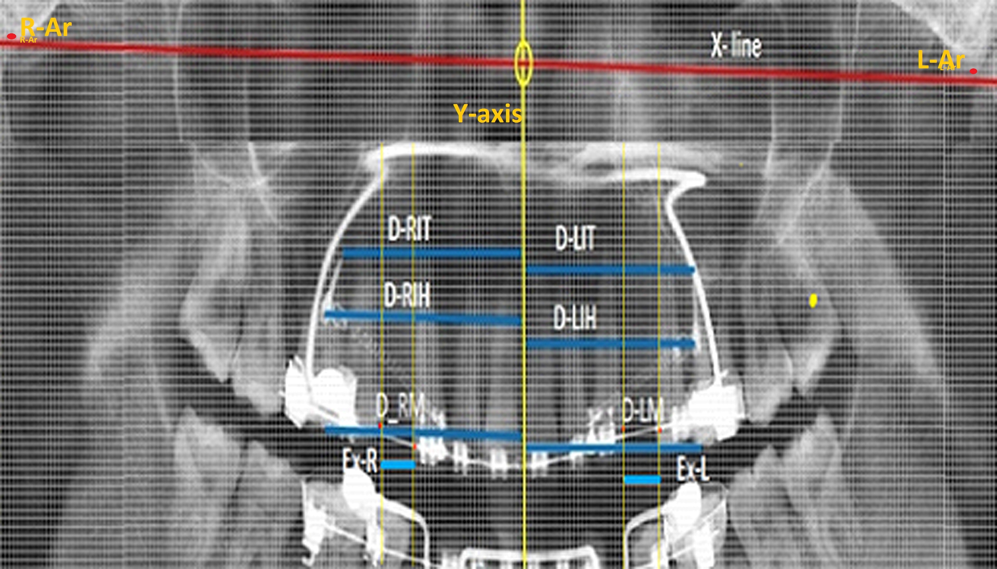
| D-RIT/D-LIT | Horizontal distance between the tail of the implant and the Y-axis on immediate side and delayed side. |
| D-RIH/D-LIH | Horizontal distance between the head of the implant and the Y-axis on immediate side and delayed side. |
| D-RM/D-LM | Horizontal distance between the mesiobuccal cusp tip ‘M’ and the Y-axis on immediate side and delayed side. |
| REX/LEX | Horizontal distance between the tangents of premolar and canine points. Indicates remaining extraction space on immediate side and delayed side. |
| D-RA/D-LA | Displacement of the anterior teeth in the distal direction on immediate side and delayed side. |
All the parameters were measured at two points of time T1 and T2. Thus, a total of 18 measurements were done. All the distances measured at T1 were designated with suffix ‘1’ and all the distances measured at T2 were designated with suffix ‘2’and were measured after three months of loading of the implant on each side. The amount of extraction space closure and the amount of retraction can be calculated from the above directly measured data. The difference of measurements (Δ) between ‘T1’ and ‘T2’ provides the relative displacement of the implant, molars and anterior teeth.
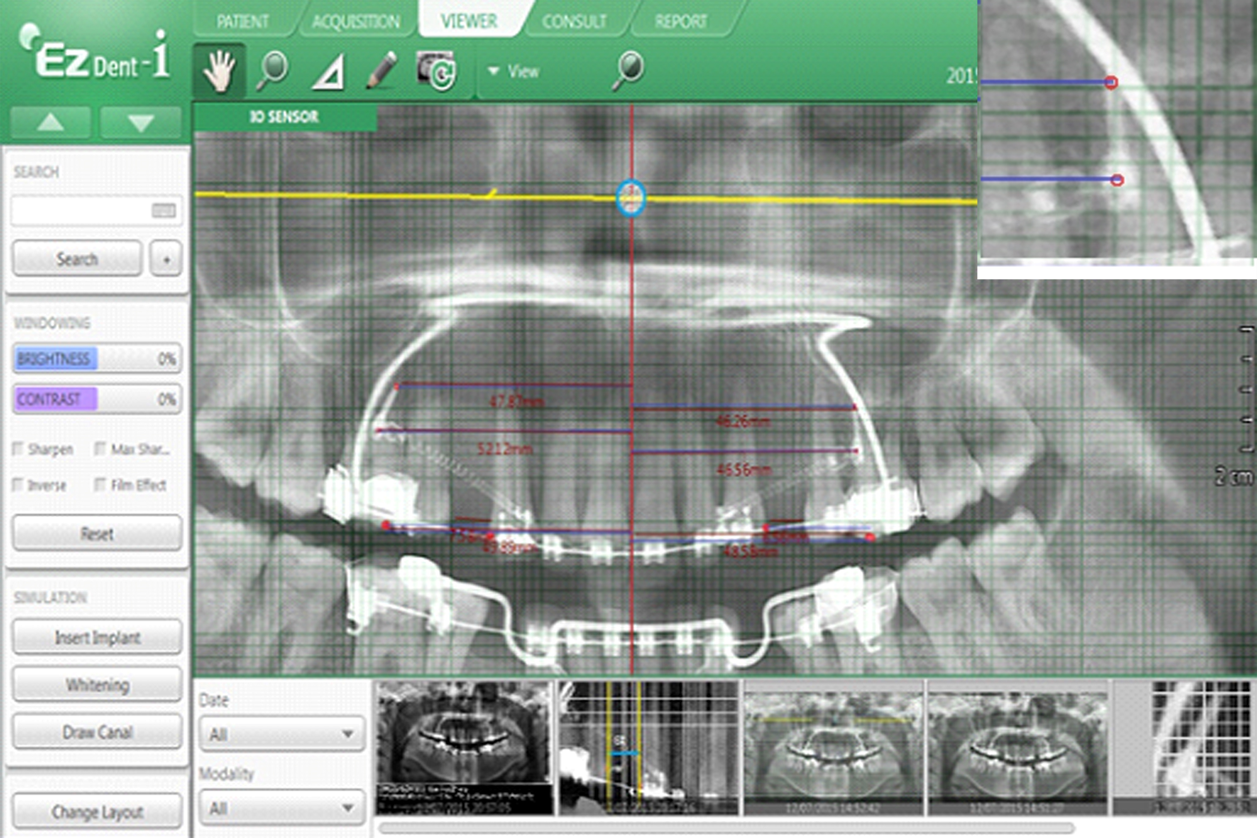
Methods of Measurement: A standard grid with each square of 1mm was superimposed with 1:1 magnification on the digital OPG using Adobe Photoshop-7 (Adobe Photo systems, Inc., Mountain View, CA). The 1mm grid corresponding to the particular landmark was again magnified and equally divided into 500 pixels (1pixel/each = 0.0394mm). Thus, the measurements can be read quantitatively precisely in millimeters up to the second decimal point directly on the computer screen. To increase the accuracy of measurements related to the implants, the digital image acquisition along with the grid was done with EZ-Dent-i software (VATECH Global, Korea) and the measurements could be read out directly on the screen [Table/Fig-6]. The average of the two methods was taken as final reading.
Image acquisition and measurements taken on ezeedent soft ware.
The calibration of the OPG was adjusted for magnification. The magnification index was 1.2 according to the manufacturer. A pilot study of a sample of five patient casts and OPGs taken at different points of time for the same patient were measured to derive the magnification factor on the OPG and was found to be 1.12 and this value was utilized in calculating the data. To assess the intra-examiner and inter-examiner reliability, the procedure was performed by two examiners on a trial basis on five samples of OPGs taken at T1 and T2. They were blinded from the information regarding the purpose of the study. Intra-examiner reliability data demonstrated a mean percentage agreement of 89% and a kappa coefficient of 0.94 indicating high reliability. In the final run the implants were placed by five operators (KV, BVN, KDS, IK, KPK) and the calibrations were made by a single examiner (NVK) who has a experience of two years in reading the OPG but he was blind to the purpose of the study.
Statistical Analysis
All data were depicted as mean ± S.D. and differences between two groups were validated by Student’s t test. The statistical test was analyzed by software SPSS PACKAGE 21. The p-value equal to or less than 0.05 was taken as statistically significant.
Results
The final analysis included only 21 cases (Females: 12; Males: 9) as four of the initial cases were dropped due to reasons such as breakage of basal arch wire, bracket failure on the canines. The head of the immediate loaded implant on the immediate side (ΔRIH) displaced 0.57mm mesially on an average where as the tail (ΔRIT) exhibited 0.75mm displacment. This difference of displacement between head and tail is found to be highly statistically significant (p=0.009) whereas, this difference is found to be not significant on the side of delayed loading with head (ΔLIH) and tail (ΔLIT) being displaced 0.35mm and 0.38mm on an average respectively [Table/Fig-7,8 and 9]. Further the anchor molar on the immediate loading side exhibited mesial displacement (ΔRM) of 0.56mm as compared to the molars on the delayed loading side (ΔLM) which read on an average 0.41mm and the findings were statistically significant (p = 0.024) [Table/Fig-10]. The amount of anterior retraction on the delayed loading side (ΔLA) is 1.46mm and is found to be 1.5 times higher than the amount of anterior retraction achieved with that immediate loading implants (ΔLA) with a mean value of 0.94mm (p<0.001) [Table/Fig-9].
Measured displacement of implants, molars and anterior teeth.
| Type of Loading | Parameter | n | Maximum(in mm) | Minimum(in mm) | Range(in mm) | Mean ± S.D(in mm) |
|---|
| Immediate Loading (R) | Tail of the implant (ΔRIT) | 21 | 1.41 | 0.25 | 1.16 | 0.75 ± 0.24 |
| Head of the implant (ΔRIH) | 21 | 0.89 | 0.07 | 0.82 | 0.57 ± 0.16 |
| Molar displacement (ΔRM) | 21 | 0.80 | 0.19 | 0.61 | 0.56 ± 0.18 |
| Anterior tooth retraction (ΔRA) | 21 | 1.30 | 0.40 | 0.90 | 0.94 ± 0.24 |
| Extraction space closure (ΔREX) | 21 | 2.00 | 0.60 | 1.40 | 1.51 ± 0.32 |
| Delayed Loading (L) | Tail of the implant (ΔLIT) | 21 | 1.20 | 0.00 | 1.20 | 0.38 ± 0.27 |
| Head of the implant (ΔLIH) | 21 | 0.70 | 0.00 | 0.70 | 0.35 ± 0.21 |
| Molar displacement (ΔLM) | 21 | 1.20 | 0.10 | 1.10 | 0.41 ± 0.23 |
| Anterior tooth retraction (ΔLA) | 21 | 2.30 | 0.30 | 2.00 | 1.46 ± 0.42 |
| Extraction space closure (ΔLEX) | 21 | 2.80 | 1.16 | 1.64 | 1.87 ± 0.35 |
Comparison of the displacement of the head and tail of the implant on the same side on to that of opposite side (Students’ ‘t’-test)
| Parameter | Mean ± S.D(in mm) | Mean Diff. | t-value | p-value |
|---|
| ΔR-IT | 0.75 ± 0.24 | 0.183 | 2.734 | 0.009* |
| ΔR-IH | 0.57 ± 0.16 |
| ΔL-IT | 0.38 ± 0.27 | 0.035 | 0.447 | 0.657** |
| ΔL-IH | 0.35 ± 0.21 |
| ΔR-IT | 0.75 ± 0.24 | 0.371 | 4.501 | <0.001* |
| ΔL-IT | 0.38 ± 0.27 |
| ΔR-IH | 0.57 ± 0.27 | 0.223 | 3.605 | 0.001* |
| ΔL-IH | 0.35 ± 0.21 |
*p < 0.05 (Significant), **p > 0.05 (Not significant) R-Immediate loading: L- Delayed loading
Comparison of the displacement of the molars and anterior tooth on same side and to that of opposite side (Students’ ‘t’-test).
| Parameter | Mean ± S.D(in mm) | Mean Diff. | t-value | p-value |
|---|
| ΔRM | 0.56 ± 0.18 | 0.154 | 2.358 | 0.024* |
| ΔLM | 0.41 ± 0.23 |
| ΔREX | 1.51 ± 0.32 | -0.366 | -3.395 | 0.002* |
| ΔLEX | 1.87 ± 0.35 |
| ΔRA | 0.94 ± 0.24 | -0.521 | -4.719 | <0.001* |
| ΔLA | 1.46 ± 0.42 |
*p < 0.05 (Significant), **p > 0.05 (Not significant) R-Immediate loading: L- Delayed loading
Comparison of the displacement of the head and tail of the implant and the molars on same side and to that of opposite side (Students’t’-test).
| Parameter | Mean ± S.D(in mm) | Mean Diff. | t-value | p-value |
|---|
| ΔRIT | 0.75 ± 0.24 | 0.189 | 2.758 | 0.009* |
| ΔRM | 0.56 ± 0.18 |
| ΔRIH | 0.57 ± 0.16 | 0.005 | 0.100 | 0.921** |
| ΔRM | 0.56 ± 0.18 |
| ΔLIT | 0.38 ± 0.27 | -0.028 | -0.350 | 0.728** |
| ΔLM | 0.41 ± 0.23 |
| ΔLIH | 0.35 ± 0.21 | -0.063 | -0.885 | 0.382** |
| ΔLM | 0.41 ± 0.23 |
*p < 0.05 (Significant), **p > 0.05 (Not significant)
*p < 0.05 (Significant), **p > 0.05 (Not significant) R-Immediate loading: L- Delayed loading
Discussion
The mini-screw implants have been employed as an absolute anchorage providers and controversy still exists on loading protocol. The present study evaluated and compared the displa-cement pattern of mini-implants and dental structures with two patterns of loading during orthodontic tooth retraction by a split mouth technique. All the measurements were obtained by a grid method superimposed on a digital OPG. This method provides direct visualisation, comparison and quantification of measurements on delayed and immediate side. The immediate side implants were loading immediately after insertion where as the delayed side implants were loading after a lag period of 15 days following its placement. The difference of displacement pattern between the two side reached statistical significance for all the parameters tested. The delayed loading implant exhibited less displacement in mesial direction as compared to immediate loading. Further it was also observed that there was variation in the reciprocation of head and tail of the immediate and delayed side implants to the retraction forces. The difference in the movement of the head and tail may be probably related to the movement created during retraction. The quality of the bone around the implant may be responsible for the difference observed between the immediate and delayed loading which warrants histological studies which are not possible in humans. Further, it was detected from the present study that the implants exhibited enhanced displacement in mesial direction on immediate loading as well as delayed loading as compared to the molars in the initial three months of the retraction. The amount of extraction space closure measured on the immediate side was 1.51mm and on the delayed loading side is 1.87mm. Thus, the amount of space closure with delayed loading implants was 1.2 times as compared to that of the immediate loading mini-implant on immediate side and the difference was found to be statistically significant (p= 0.002). The relative contribution of the extraction space closure by distal movement of anteriors and mesial movement of molars on each side was analysed. Molars on immediate side displaced medially on average of 0.6mm as compared to the distal movement of the anterior teeth (0.90mm) in the ratio 38:62. On delayed loading side this contribution was marked as 23% by molars (0.41mm) and 77.13% by distal retraction of the anterior teeth (1.46mm). Accordingly the proposed null hypothesis stands rejected.
The present study was in agreement with the metadata analysis of Ohashi E which concluded that loading protocols for implants involve a minimum waiting period of two months before applying orthodontic forces while loading protocols for mini-implants or screws involve a minimum waiting period of two weeks [15]. The results of the current study are in tune with the findings of the study of Zhanga L which concluded that delayed loading is recommended for application of orthodontic forces [16].
However, the findings of the present study contradicts the observation of Romanos GE who demonstrated that immediate loading increased the ossification of the alveolar bone around the implant and concluded that immediate loading might have contributed to the good prognosis of mini-screw implants [17].
The mini-screws were not an absolute anchorage, like an endosseous implant. The displacement could be attributed to several factors, such as fixture size, orthodontic force magnitude, depth of the mini-screw inside the implant site, bone quality and quantity at the implant site, and waiting period. Among these factors, the waiting period might play a determining role in displacement. However, no mini-screws in this study was loosened or failed during the treatment.
The displacement of mini-screws would be a serious matter when the displacement harms adjacent vital structures, such as dental roots, nerves, and blood vessels. When mini-screws are placed in a tooth-bearing area, a clearance of 1.5mm between the mini-screw and the dental root is recommended for safety, based on the finding of this study. The waiting period was two weeks in this study. Apparently two weeks were long enough for soft tissue healing but not long enough for osseointegration. It has been shown histologically that, when the load was placed prematurely, a layer of fibrous tissue would interpose at the bone-implant contacts [18].
Limitation
There are certain drawbacks of the present study. This clinical study was based on the measurement done on the OPG. There are inherent errors associated with the OPG in measuring linear displacements in horizontal direction. However, this was overcome by calibration of magnification factor directly on the models of the same patients on whom OPG was taken. The angulation of implant insertion was not precisely mentioned. This may also contribute to the anchorage loss. The exact tissue reaction at the peri-mini-implant contact surface could not be determined by the present study.
Conclusion
This study demonstrated that Orthodontic mini-implants loading after a waiting period of two weeks have mechanical advantage over the immediate loading implants. The delayed loading is beneficial as compared to the immediate loading in terms of space closure for Type A anchorage cases. The head and tail on the immediate loading has varied displacements where as on the delayed loading the displacement is tandem. The amount of extraction space closure is rapid for delayed loading as compared to the immediate loading in the first three months of retraction after loading. Further studies are warranted to directly asses the reciprocal effects of the different types of loading by utilizing modern state of art such as Cone Beam Computer Tomography (CBCT) imaging techniques.
*p < 0.05 (Significant), **p > 0.05 (Not significant) R-Immediate loading: L- Delayed loading
*p < 0.05 (Significant), **p > 0.05 (Not significant) R-Immediate loading: L- Delayed loading
*p < 0.05 (Significant), **p > 0.05 (Not significant)
*p < 0.05 (Significant), **p > 0.05 (Not significant) R-Immediate loading: L- Delayed loading