A Unique Flask Design for Processing Cranial Prosthesis Using Heat Cured Acrylic - A Case Report
Godwin Clovis Da Costa1, Meena Ajay Aras2, Paul Chalakkal3
1 Lecturer, Department of Prosthodontics, Goa Dental College & Hospital, Bambolim, Goa, India.
2 Professor & Head, Department of Prosthodontics, Goa Dental College & Hospital, Bambolim, Goa, India.
3 Assistant Professor, Department of Pedodontics & Preventive Dentistry, Goa Dental College & Hospital, Bambolim, Goa, India.
NAME, ADDRESS, E-MAIL ID OF THE CORRESPONDING AUTHOR: Dr. Paul Chalakkal, Assistant Professor, Department of Pedodontics & Preventive Dentistry, Goa Dental College & Hospital, Bambolim, Goa - 403202, India.
E-mail: atomheartpaul@yahoo.com
In a 30 year old male patient, the absence of a cranial bone fragment had left the brain covered only by dura mater, subcutaneous tissue and scalp, resulting in aesthetic and functional impairment. A prosthetic replica of the bone fragment made of PMMA (Polymethylmethacrylate) was fabricated using a unique flask design that consisted of a medium sized stainless steel instrument tray with lid, four large headed screws and a C clamp, since the prosthesis was too big to be invested in a conventional flask.
Cranial implant, Polymethylmethacrylate prosthesis, Stainless steel tray
Case Report
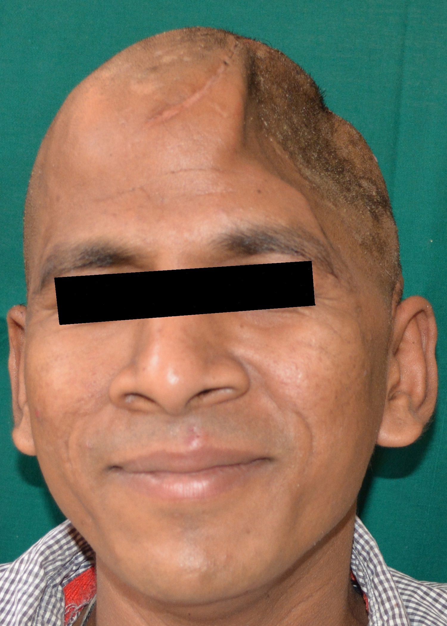
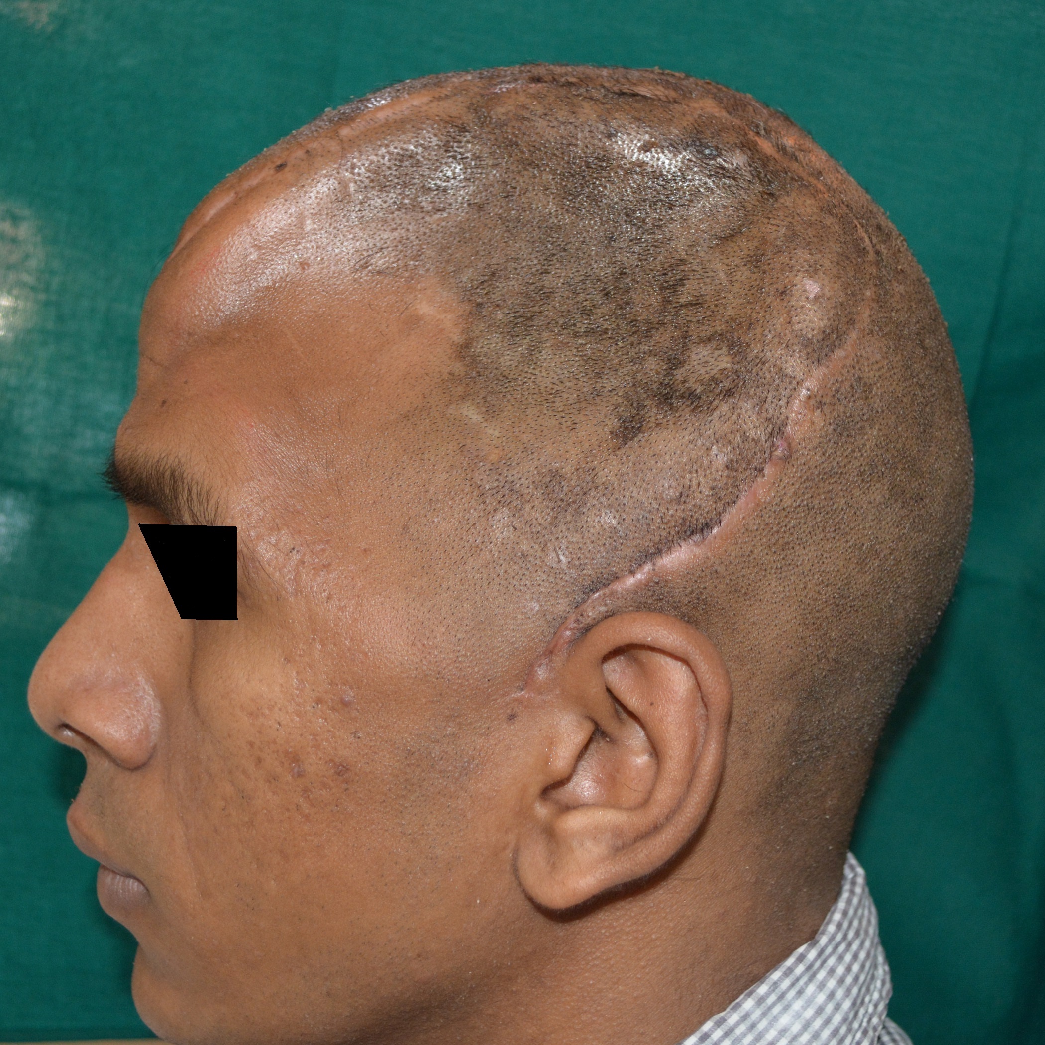
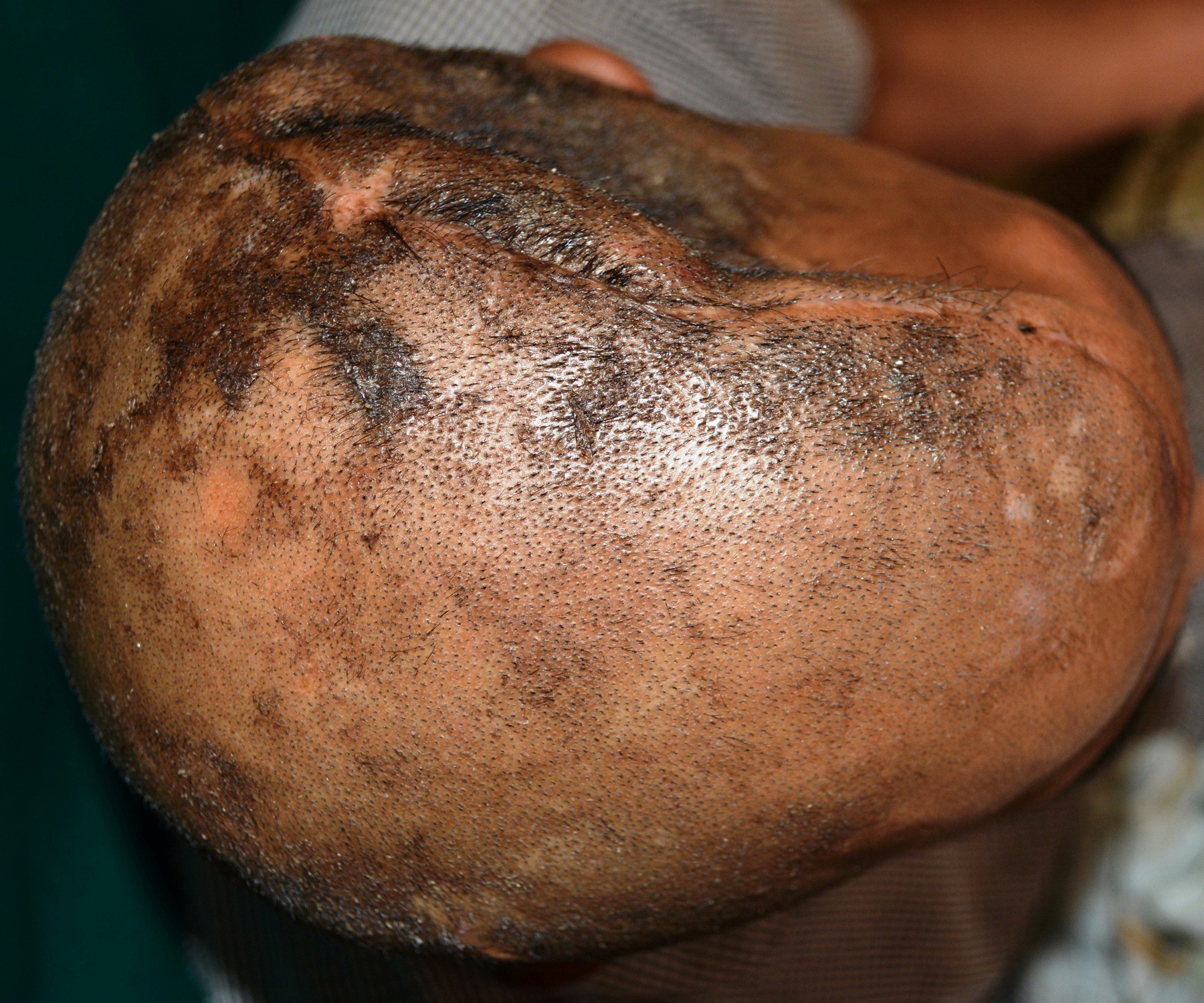
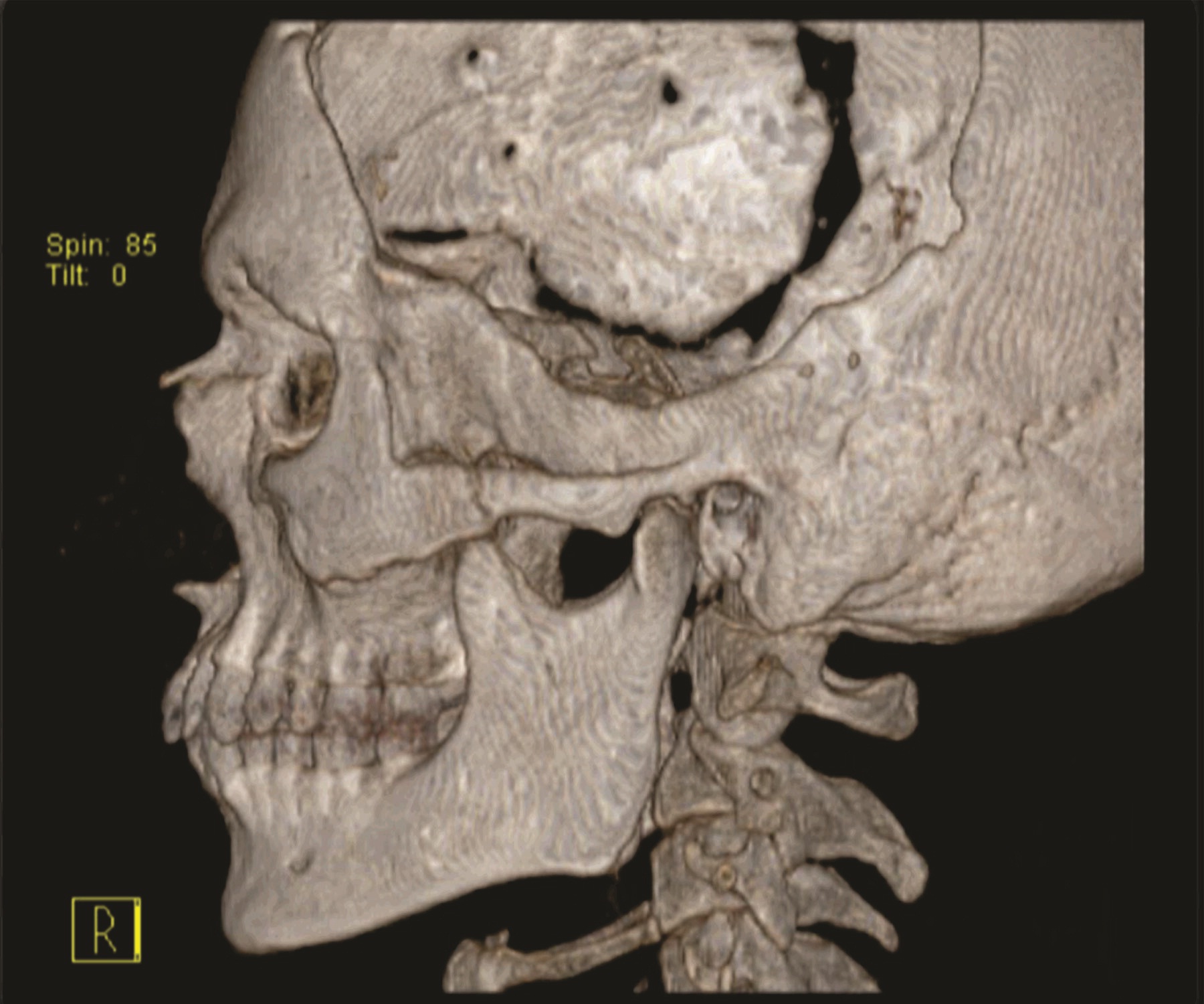
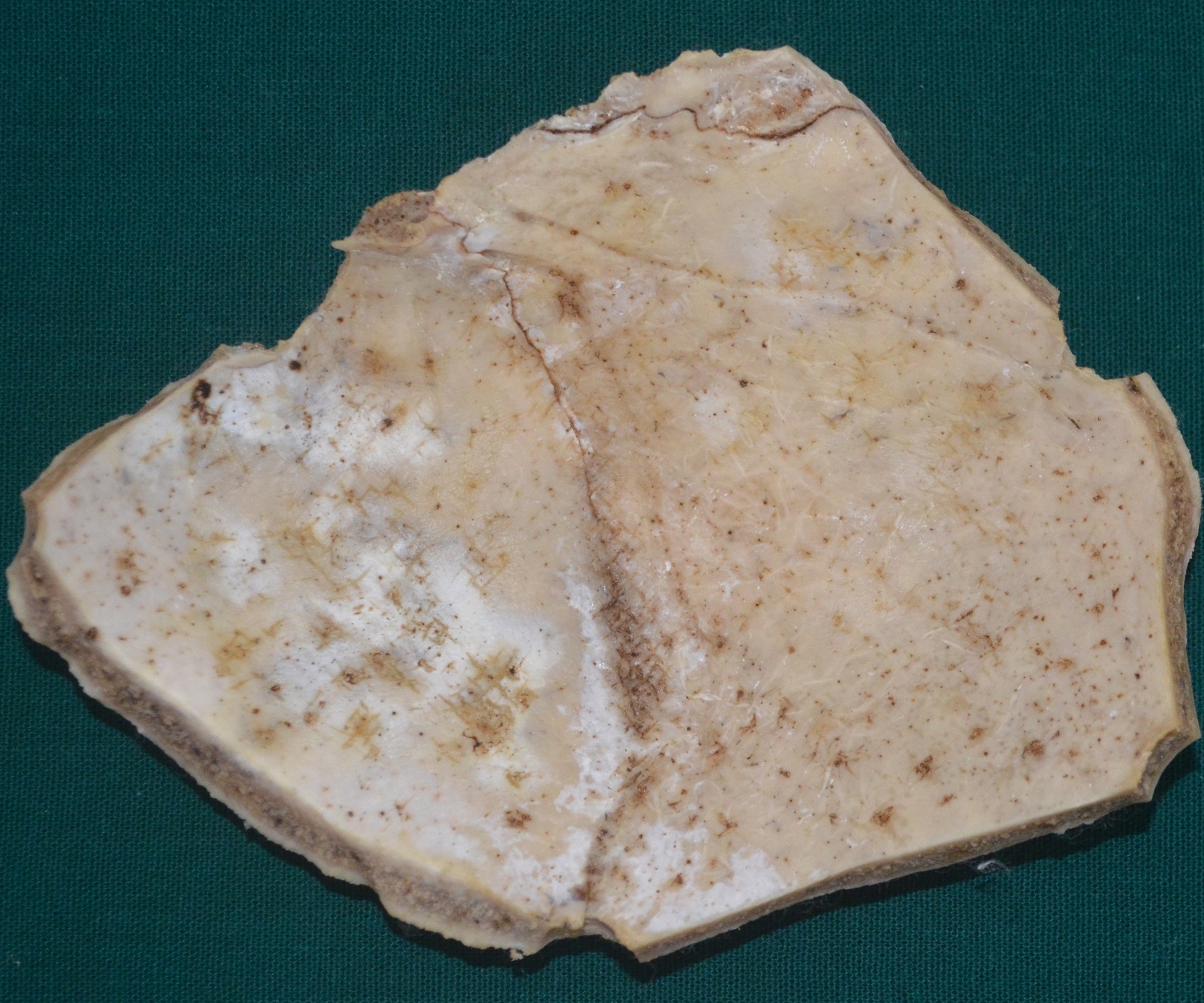
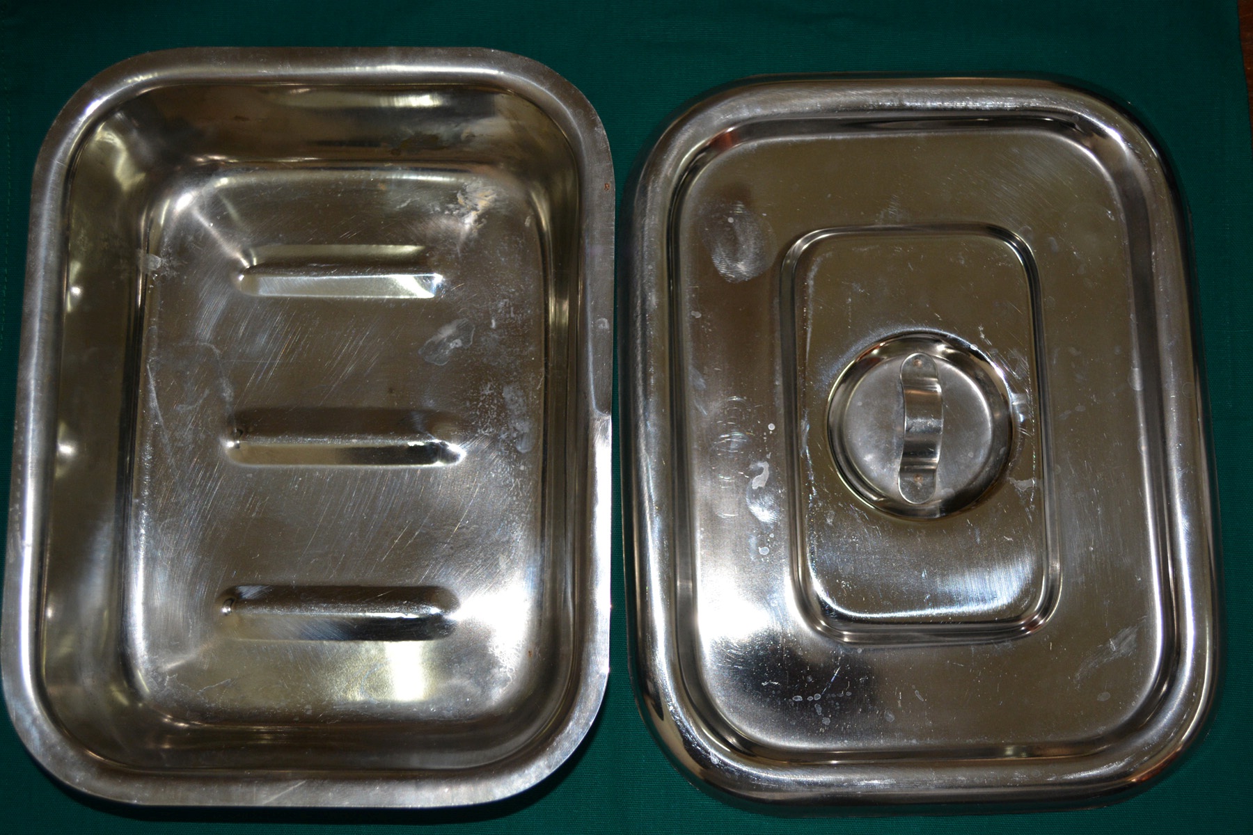
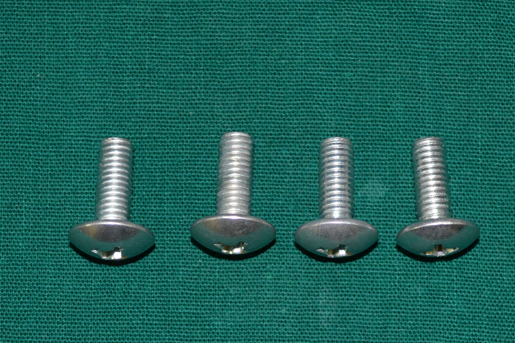
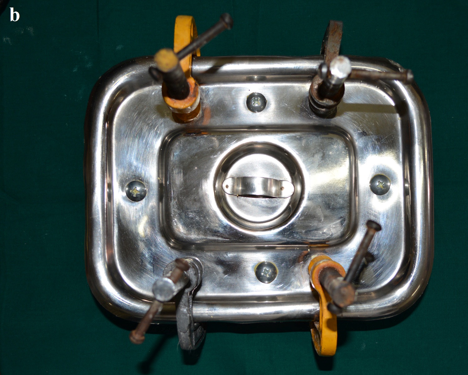
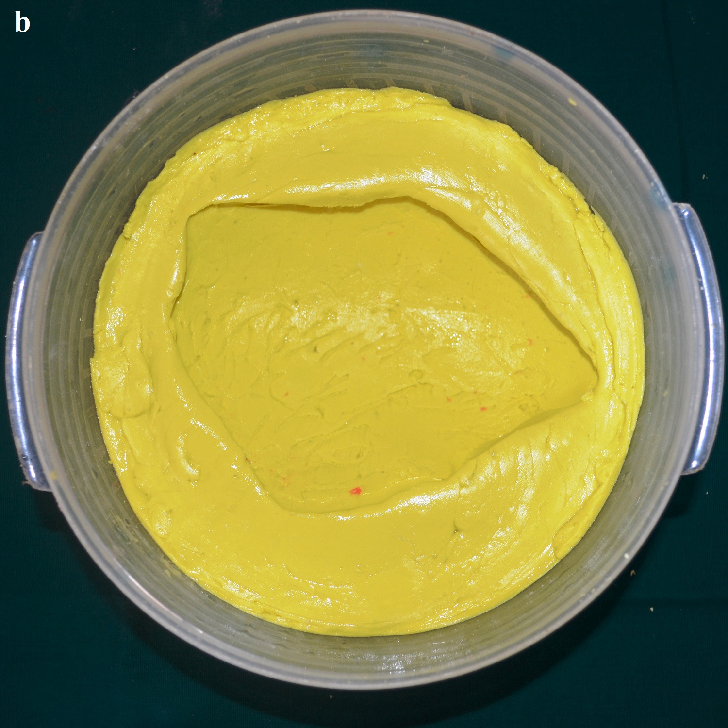
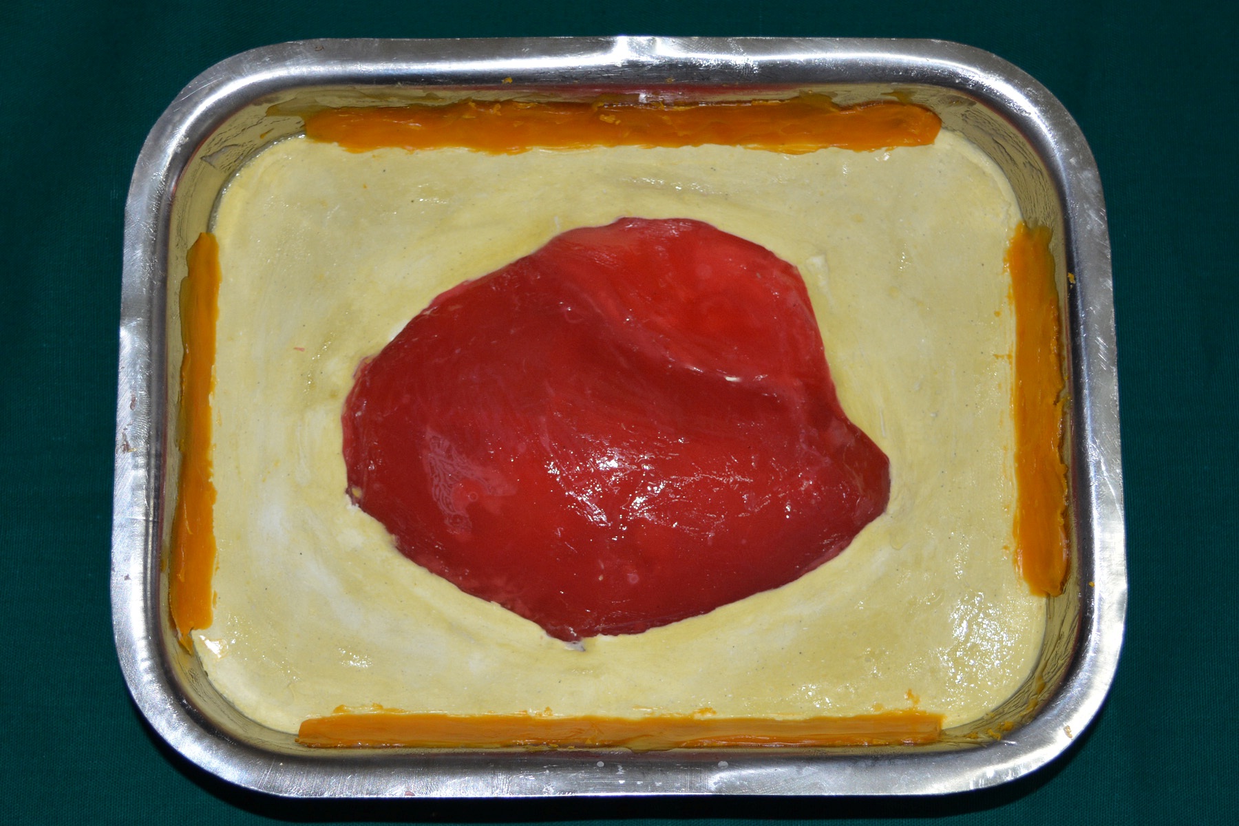
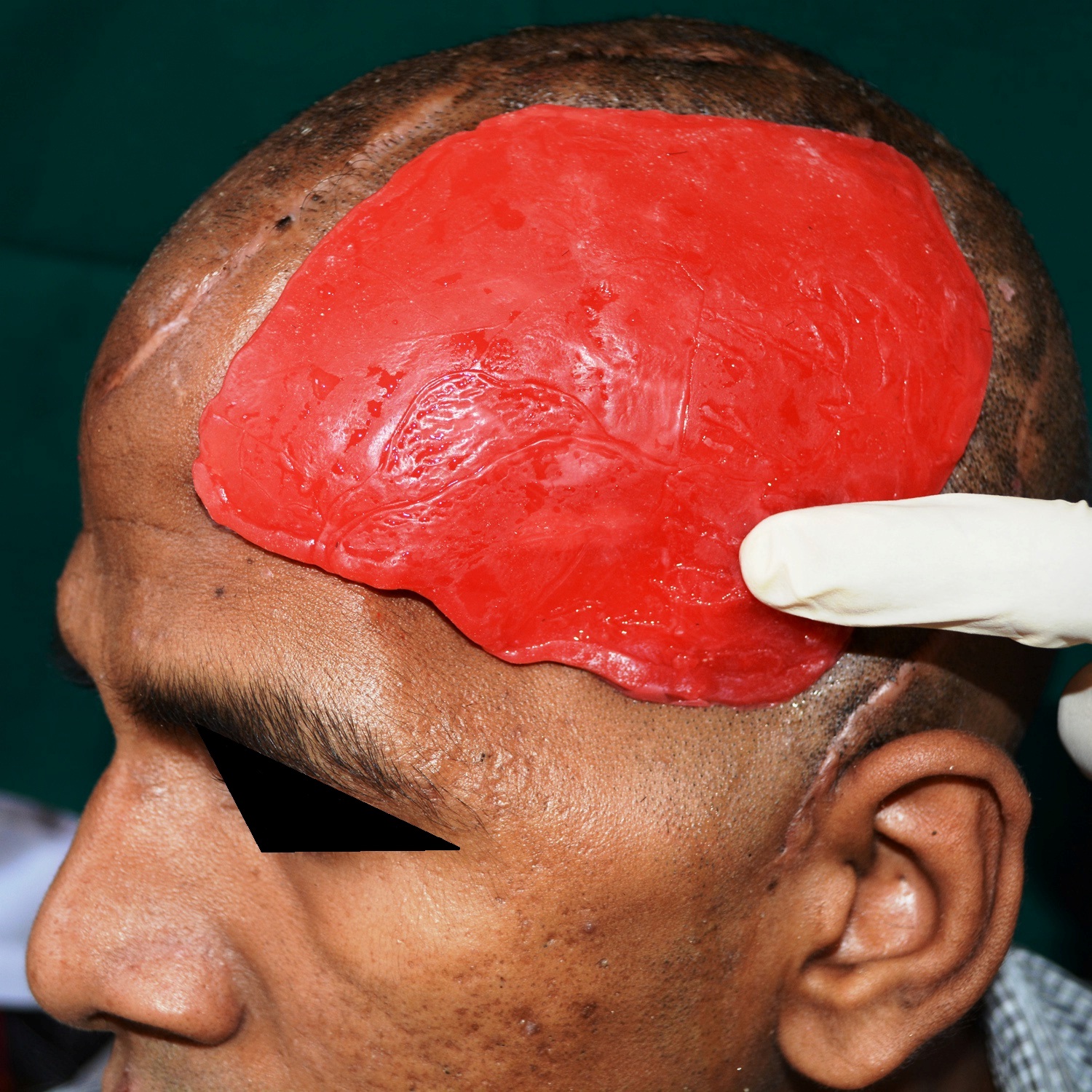
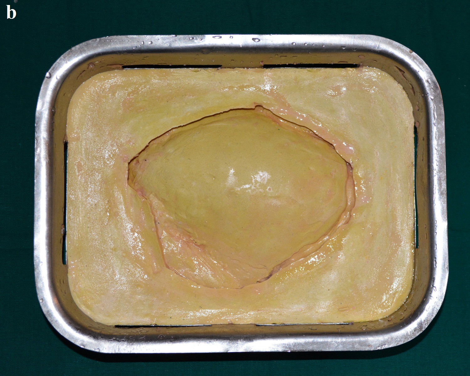
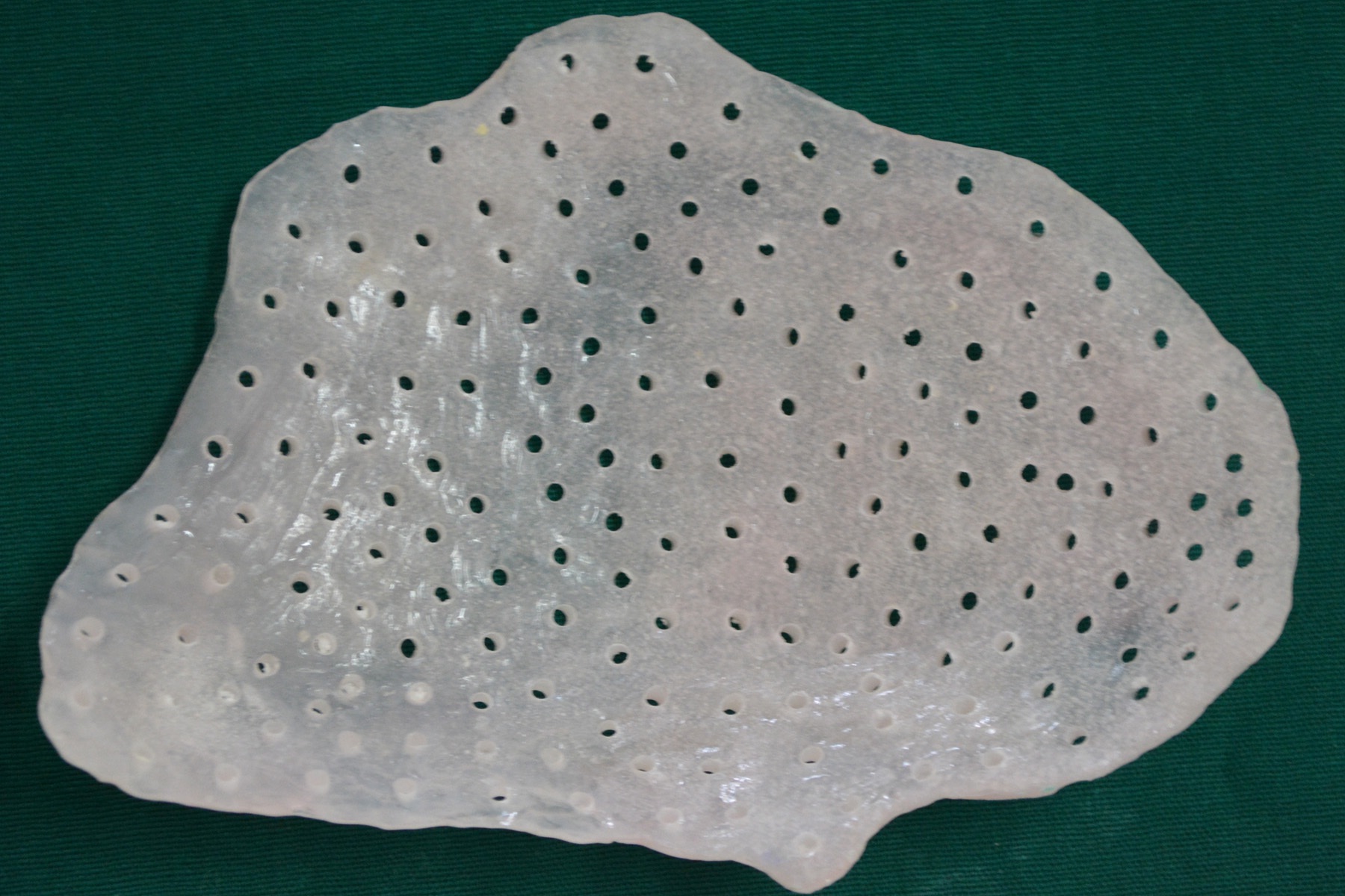
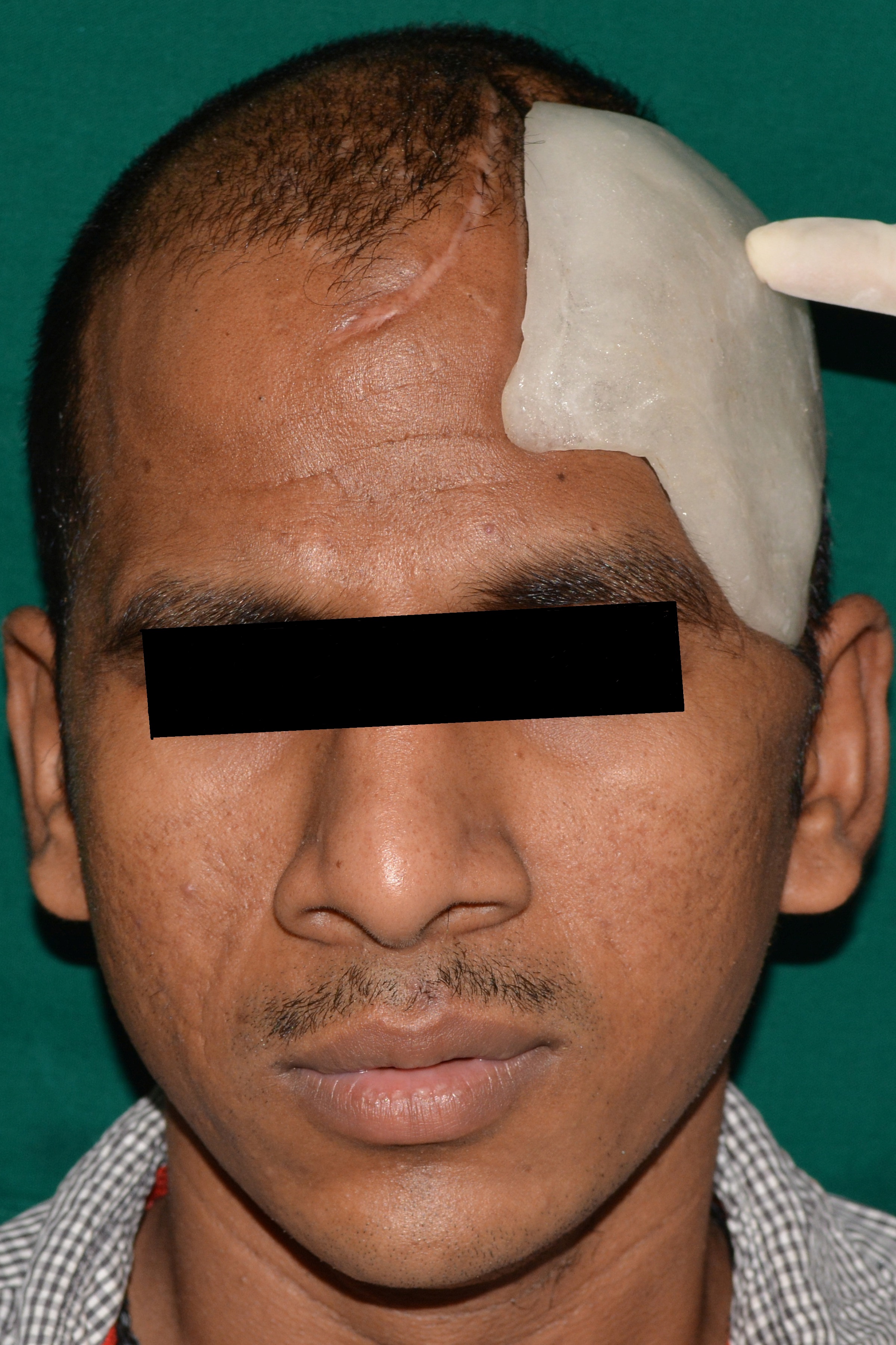
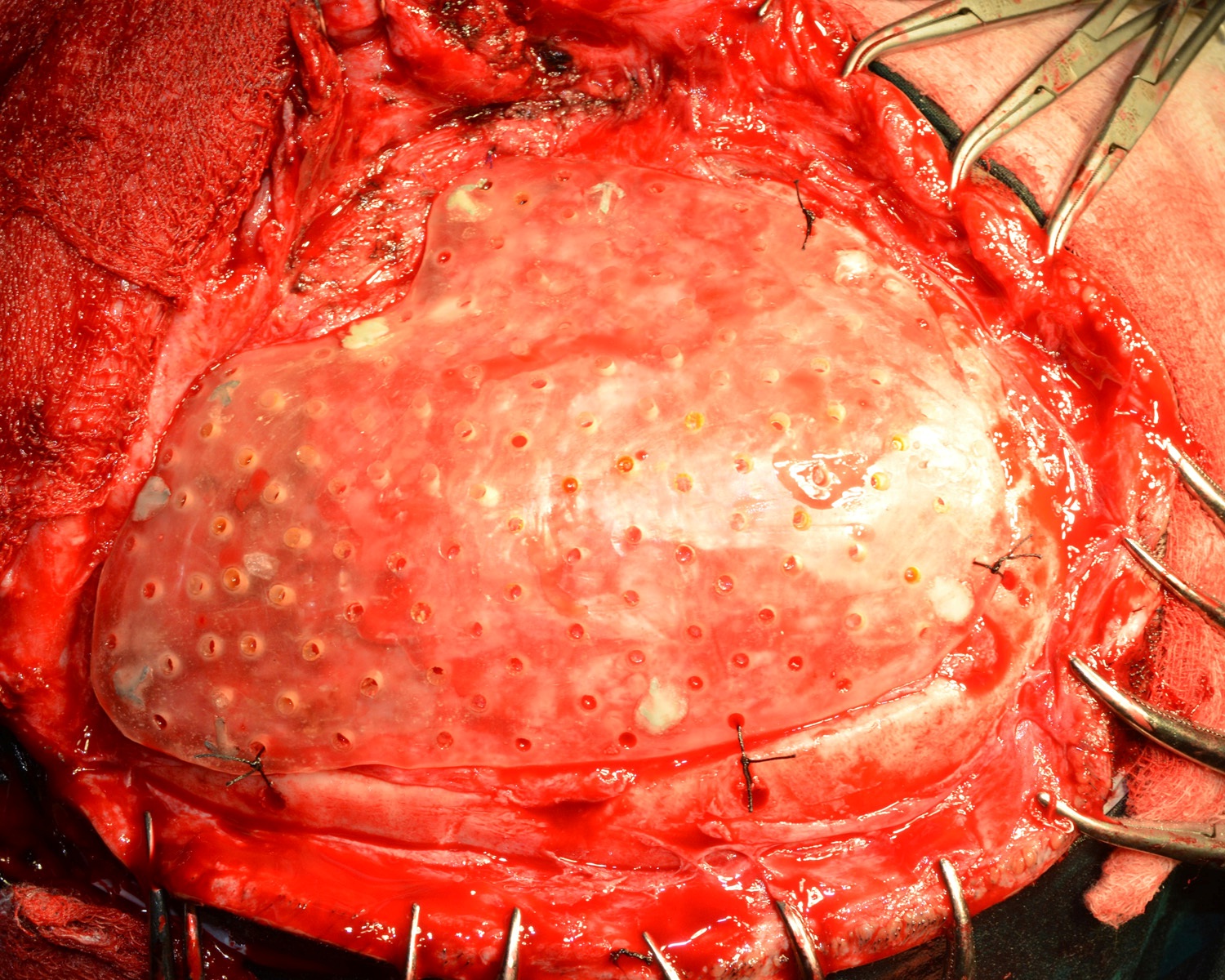
A 30 year old male patient was referred to the Department of Prosthodontics, for the rehabilitation of a cranial defect involving the left frontal and temporal bones measuring 6 inches x 4 inches [Table/Fig-1,2 and 3]. A Computed Tomography scan confirmed the cranial defect [Table/Fig-4]. The patient had brought the missing bone fragment along with him [Table/Fig-5]. A case history revealed that the fragment was not restored in its defect at the time of the surgery since the bone fragment was found to be infected. It was decided to fabricate a replica (prosthesis) of the bone fragment using PMMA, such that it could be reattached in its anatomical position. The procedure was undertaken using a unique flask design that consisted of a medium sized stainless steel instrument tray with lid [Table/Fig-6], four large headed screws (5mm in diameter) [Table/Fig-7] and a C clamp (Taparia C-Clamps 4", India) [Table/Fig-8a,8b]. Slots measuring 3mm x 127mm were cut out at approximately half the height of the tray to enable acrylic flash to flow out during the packing process. Four holes of 5mm in diameter were drilled into the lid for insertion of the screws and also for allowing the excess stone to flow out while closing after the second pour. The bone fragment was disinfected using 2% gluteraldehyde. An impression of the bone fragment was made using alginate (Zelgan, Dentsply) [Table/Fig-9a,9b]. Molten modeling wax (Deepti Dental Products, India) was poured into the impression to obtain the wax pattern of the prosthesis [Table/Fig-10]. The trial of the wax pattern was carried out to verify the borders and its external contour [Table/Fig-11]. The wax pattern was then processed using the unique flask design. The wax pattern was invested with first pour of stone (Type III Dental Stone; Kalabhai, India) up to the level of the slots. All holes were blocked with wax (Beading Wax, MDM Corporation, Delhi) to prevent dental stone from flowing out through them during the second pour. Separating media was applied over the first pour and the second pour was completed using type III dental stone. After the second pour, the lid was placed over the tray and the four screws were inserted into the setting stone. The screws helped in engaging the stone in order to provide easy retrieval after dewaxing. The clamp was tightened over and beneath the steel tray with lid. The wax pattern was dewaxed [Table/Fig-12a,12b]. Clear acrylic (DPI, India) was mixed and packed into the mould space. The clamp was tightened until flash was observed from the slots on all four sides of the tray. The flask was then processed by the compression moulding technique using the long curing cycle of 8 hours at 74°C, following which the heat cured PMMA implant was retrieved. Perforations of 2.5mm diameter were made on the implant at intervals of approximately 3mm from one another [Table/Fig-13], following which, it was tried on the external surface of the defect [Table/Fig-14]. The implant was finished, polished and autoclaved.
Anterior view of the cranial defect.
Left lateral view of the cranial defect.
Superior view of the cranial defect.
CT scan of the cranial defect.
Stainless steel instrument tray with lid.
Lateral view of C clamp engaging the tray.
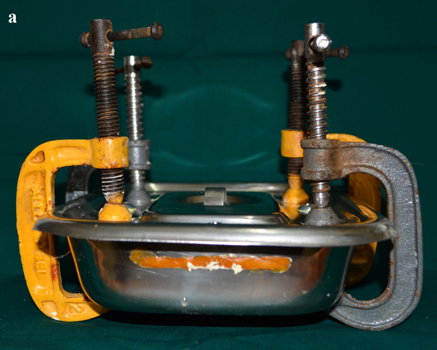
Superior view of C clamp engaging the tray.
Bone fragment placed in alginate.
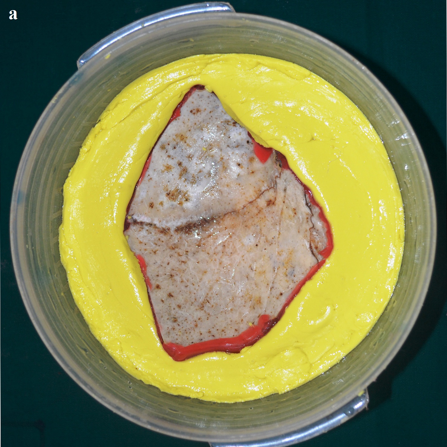
Impression of the bone fragment.
Modeling wax in the impression.
Trial of wax pattern on the external surface of the defect.
Flask with mold space after dewaxing.
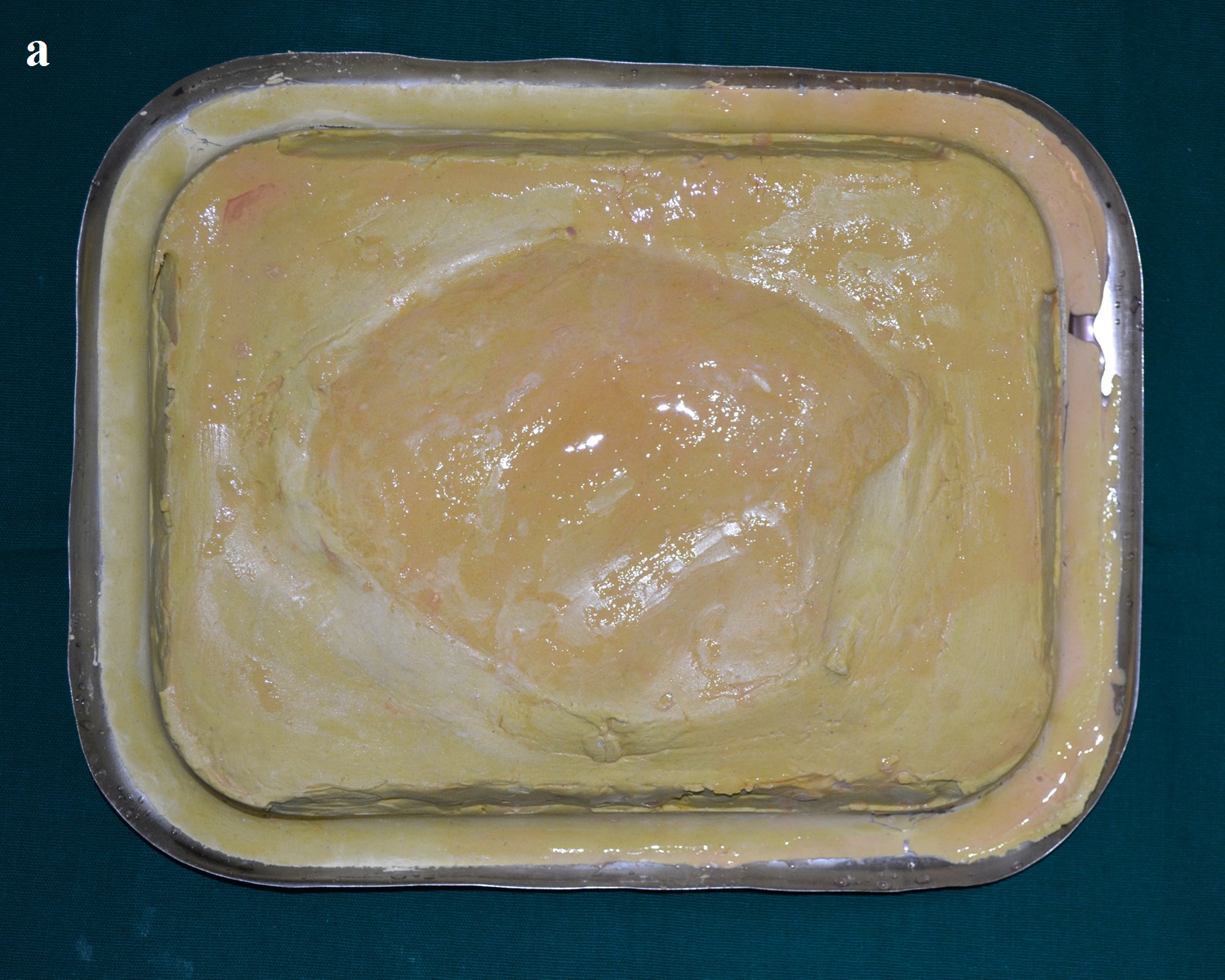
Second pour with dental stone.
PMMA prosthetic implant with perforations
PMMA implant tried on the external surface of the cranial defect.
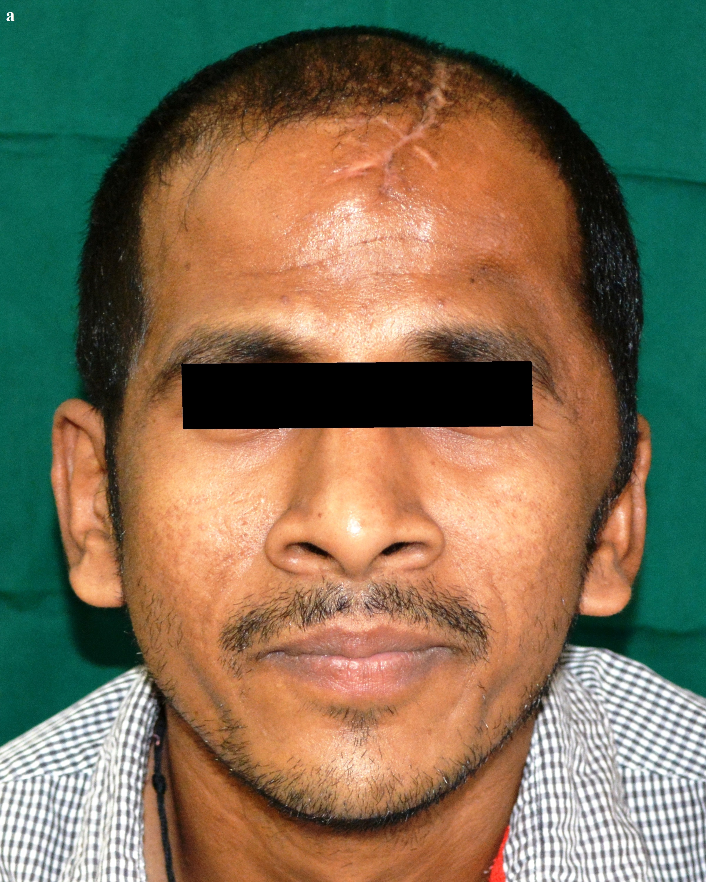
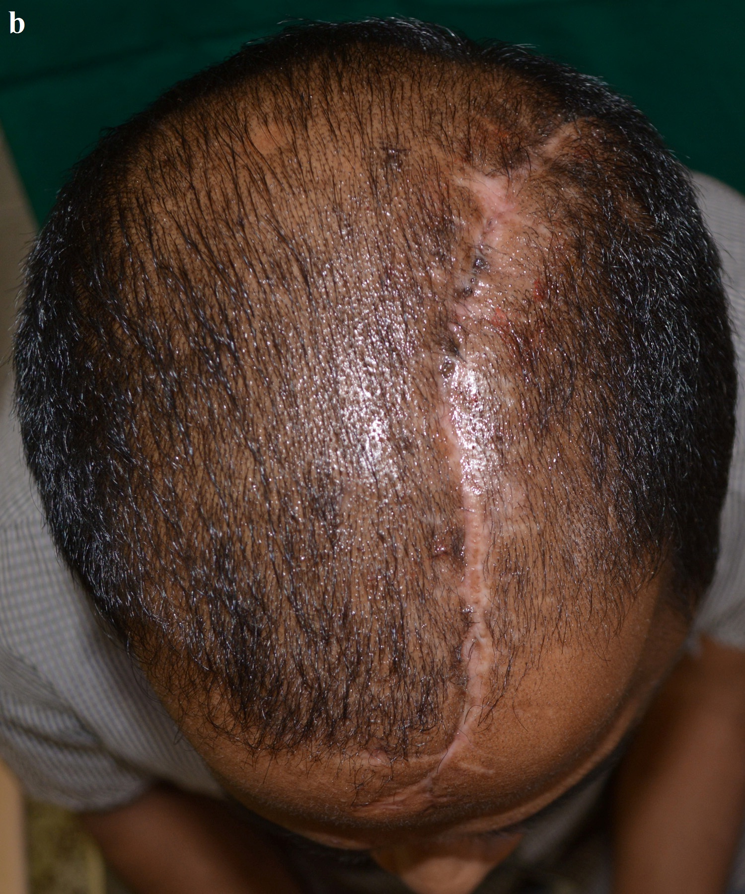
The surgery was carried out under general anaesthesia by a Neurosurgeon. The scalp tissues were raised by blunt dissection to expose the defect, in order to enable adequate vascular supply. The cranioplasty was performed beginning with a bi-coronal approach raising a mucoperiosteal flap, without causing any dural damage. By sharp dissection, a plane was developed between the dura and the overlying fibrous connective tissue of the scalp. A periosteal elevator was used to free the soft tissue and expose the bony margins. The PMMA cranial prosthesis was then checked for adaptation in the defect. Minor corrections were made in the prosthesis with the help of a micromotor using saline irrigation under sterile conditions, without contamination of the tissues with acrylic particles. Suturing of the prosthesis was carried out through the previously made perforations using vicryl resorbable sutures (Medline Industries, India) [Table/Fig-15]. Haemostasis was achieved using high volume suction (Acu-Vac) and wound closure was completed using silk suture material. The silk suture material was removed after 10 days. Post-operative recovery was uneventful. The patient was satisfied with the procedure, both aesthetically and functionally [Table/Fig-16a,16b]. The patient has been monitored at monthly intervals for the last two years [Table/Fig-17].
Surgical placement of the implant with sutures.
Post-operative anterior view.
Post-operative superior view.

Discussion
In the absence of the bone fragment, the brain is covered only by dura mater, subcutaneous tissue and the scalp, resulting in aesthetic and functional impairment. The imperfection makes the person susceptible to trauma, seizures and meningitis [1]. Cranioplasty is a neurosurgical procedure performed to cover an injured bone in the skull in order to restore aesthetics and psychological stability, protect the underlying brain, and to maintain intracranial pressure relationships [2,3]. However, one of the greatest benefits following cranioplasty is the improvement in neurologic function, which was proven by an increase in the Glasgow Outcome Scale from 3 to 4. It was attributed to changes in brain physiology resulting from improved cerebral blood flow, cerebrovascular reserve capacity and cerebral glucose metabolism [4]. Heat cure PMMA has been used extensively for cranioplasty [5–8]. The advantages are inertness, color stability, cost effectiveness, adjustability (even during surgery), and that they do not produce artifacts on CT or MRI [9]. However, radiolucency remains a major disadvantage, since PMMA fractures cannot be identified on a radiograph [10]. Although residual monomer is known to leach out from cold cure acrylic resulting in cytotoxicity [11], the residual monomer in heat-cured acrylic is unlikely to leach out on immersion in water [12]. Processing PMMA using the long curing cycle of 8 hours at 74°C reduces the residual monomer in the prosthesis [9,13]. Perforations of 2.5mm diameter were made on the implant at intervals of approximately 3mm from one another to allow accumulated fluid to seep out into the sub-galeal space, permit adhesions between the prosthesis and the soft tissue, and allow adequate blood supply to the overlying scalp [9,10].
Conclusion
In this case report, an innovative steel tray flask design was used to fabricate the prosthesis, since the bone fragment/prosthesis was too big to be invested in the conventional flask. All articles in literature related to cranial prosthesis fabrication, mention of impressions made from the cranial defect. None of these authors have made an impression from a fractured bone fragment. This is the uniqueness of the present method, wherein alginate impression material was used to record the impression of the fragment. Moreover, cost effectiveness and ease of availability are also advantages of the steel tray flask design.
[1]. Chacón-Moya E, Gallegos-Hernández JF, Piña-Cabrales S, Cohn-Zurita F, Goné-Fernández A, Cranial vault reconstruction using computer-designed polyetheretherketone (PEEK) implant: case reportCir Ciruj 2009 77:437-40. [Google Scholar]
[2]. Saldarriaga JF, Vélez SC, Posada AC, Henao BB, Valencia CA, Design and manufacturing of a custom skull implantAm J Eng Appl Sci 2011 4(1):169-74. [Google Scholar]
[3]. Joffe JM, Nicoll SR, Richards R, Linney AD, Harris M, Validation of computer-assisted manufacture of titanium plates for cranioplastyInt J Oral Maxillofac Surg 1999 28:309-13. [Google Scholar]
[4]. Dujovny M, Aviles A, Agner C, Fernandez P, Charbel FT, Cranioplasty: Cosmetic or therapeutic?Surg Neurol 1997 47:238-41. [Google Scholar]
[5]. Solaro P, Pierangeli E, Pizzoni C, Boffi P, Scalese G, From computerized tomography data processing to rapid manufacturing of custom-made prostheses for cranioplasty: case reportJ Neurosurg Sci 2008 52(4):113-16. [Google Scholar]
[6]. Joffe JM, Mcdermott PJC, Linney AD, Mosse CA, Harris M, Computer-generated titanium cranioplasty: report of a new technique for repairing skull defectsBr J Neurosurg 1992 6:343-50. [Google Scholar]
[7]. Yanai A, Resin sealant: a new method of methyl methacrylate cranioplasty. Technical noteJ Neurosurg 1991 75:328-30. [Google Scholar]
[8]. Gronet PM, Waskewicz GA, Richardson C, Preformed acrylic cranial implants using fused deposition modeling: A clinical reportJ Prosthet Dent 2003 90:429-33. [Google Scholar]
[9]. Simon P, Mohan J, Selvaraj S, Saravanan BS, Pari P, Craniofacial prosthetic reconstruction using polymethylmethacrylate implant: A case reportJ Indian Prosthodont Soc 2014 14(1):S303-07. [Google Scholar]
[10]. Prithviraj DR, Anish G, Sumit K, Pujari M, Garg P, Combined surgical and prosthetic approach for rehabilitation of frontonasal defect using custom made titanium implant: a case reportJ Clin Exp Dent 2011 3(l1):e382-85. [Google Scholar]
[11]. Tsuchiya H, Hoshino Y, Tajima K, Takagi N, Beaching and cytotoxicity of formaldehyde and methylmethacrylate from acrylic resin denture base materialsJ Prosthet Dent 1984 71:618-24. [Google Scholar]
[12]. Austin AT, Basker RM, The level of residual monomer in acrylic denture base materials: With particular reference to a modified method of analysisBr Dent J 1980 :281-86. [Google Scholar]
[13]. Anusavice JK. Phillip’s Science of Dental Materials (Ch-22), 11th edn. Elsevier, St. Louis, 2003 p 733 [Google Scholar]