An Innovative Method of Assessing the Mechanical Axis Deviation in the Lower Limb in Standing Position
Jagannath Kamath1, Raja Shekar Danda2, Nikil Jayasheelan3, Rohit Singh4
1 Professor, Department of Orthopaedics, Kasturba Medical College, Manipal University, Mangalore, Karnataka, India.
2 Senior Resident, Department of Orthopaedics, Kasturba Medical College, Manipal University, Mangalore, Karnataka, India.
3 Senior Resident, Department of Orthopaedics, Kasturba Medical College, Manipal University, Mangalore, Karnataka, India.
4 Senior Resident, Department of Orthopaedics, Kasturba Medical College, Manipal University, Mangalore, Karnataka, India.
NAME, ADDRESS, E-MAIL ID OF THE CORRESPONDING AUTHOR: Dr. Raja Shekar Danda, Senior Resident, Department of Orthopaedics, Kasturba Medical College Mangalore, Manipal University, Karnataka-576104, India.
E-mail: rajudanda08@gmail.com
Introduction
Various methods of measuring mechanical axis deviation of lower limb have been described including radiographic and CT scanogram, intraoperative fluoroscopy with the use of an electrocautery cord. These methods determine the mechanical axis in a supine, non-weight bearing position. Although long cassette standing radiographic view is used for the purpose but is not available at most centres. A dynamic method of determining the mechanical axis in a weight bearing position was devised in this study.
Aim
The aim of the study was to describe a simpler and newer method in quantifying the mechanical axis deviation in places where full length cassettes for standing X rays are not available.
Materials and Methods
A pilot study was conducted on 15 patients. The deviation from the mechanical axis was measured using a manually operated, hydraulic mechanism based, elevating scissor lift table. Patient was asked to stand erect over the elevating lift table with both patellae facing forward and C-arm image intensifier was positioned horizontally. Radiological markers were tied to a radio-opaque thread and placed at the centre of head of the femur and another at the centre of the tibio-talar joint. C-arm views of the hip, ankle and knee joint were taken to confirm the correct position of the marker by varying the height of the lift table.
Results
The mechanical axis deviation values were recorded by measuring distance between the centre of the knee and radio-opaque thread in cm. This was measured in each case both clinically and from the image on the monitor. The two values were found to be statistically same. Pain was measured on VAS. Mechanical axis deviation values and VAS score were found to be positively significantly correlated.
Conclusion
This technique is dynamic, unique and accurate as compared to other methods for assessing mechanical axis deviation in a weight bearing position.
C-arm imaging, Deformity, Lateral compartment
Introduction
By definition a line joining the centre of the hip (femoral head) and that of the centre of the dome of the talus is referred to as mechanical axis. The centre of the knee joint should generally pass through this line. This neutral mechanical axis alignment ensures equal weight transmission through the medial and lateral compartments of the knee. If the mechanical axis passes medial or lateral to the centre of the knee there will be corresponding increased force transmitted across the medial or lateral compartment of the knee. Clinically and radiologically expressed as varus or valgus knee. In normal activities of the daily living the forces acting on the tibio-femoral and patello-femoral joint may range from 3-7 times the body weight. During normal locomotion with the centre of gravity acting, there is adduction movement acting at the knee joint. Hence the medial compartment of the knee is overloaded by 50% compared to the lateral compartment. This explains the fact that in about 90% of primary Osteoarthritis (OA) in the knee starts in the medial compartment [1].
Some studies of complicated fractures have provided early evidence that alignment may influence development and progression of knee OA [2]. The progression of primary OA knee is closely related to the mechanical axis of lower limb [3]. The association between varus and valgus malalignment and the incidence of primary tibio-femoral lateral compartment (OA) is less certain. This correlation is also complicated by the severity of the OA change and it is known that the role played by the malalignment may be more important in moderate and severe than mild variety of OA [4]. Mechanical axis deviation is described as medial or lateral malalignment. It is the distance between the centre of the knee and the mechanical axis line with a proposed normal value of 10 mm medial (range, 3 to 17 mm medial) [5].
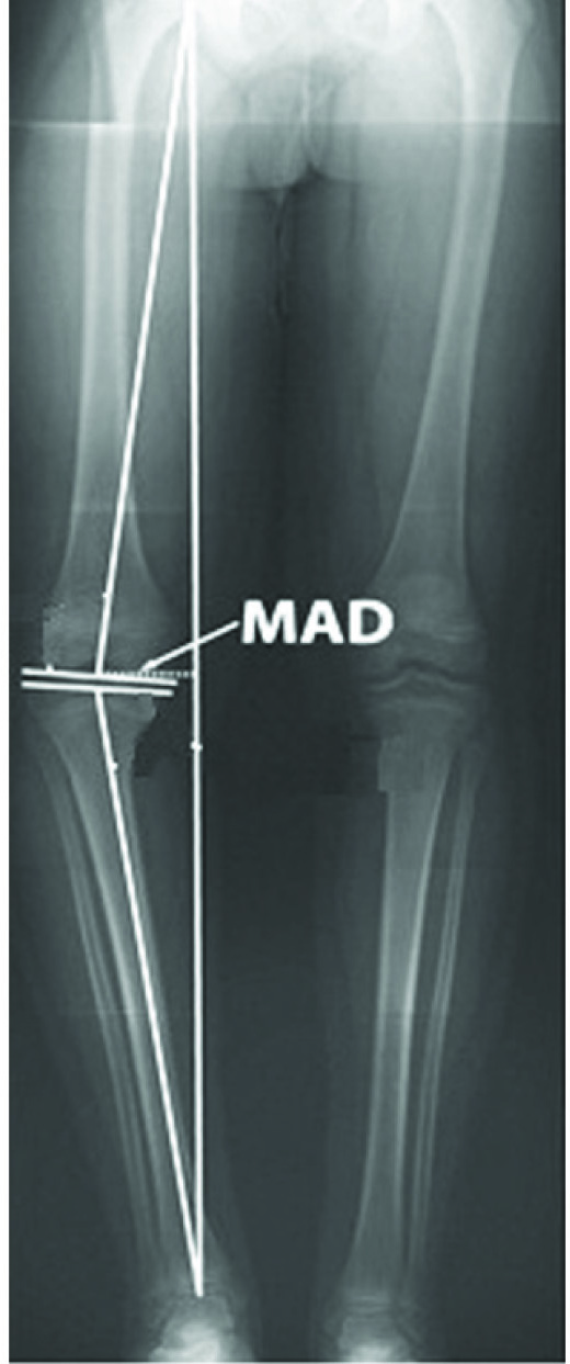
Various methods of measuring mechanical axis deviation of lower limb have been described. These include radiographic and CT scanogram, computer assisted navigational tools, intraoperative fluoroscopy with the use of an electrocautery cord [6]. These methods determine the axis in a supine, non-weight bearing position. There was a need to address this and devise a dynamic method of determining the axis in a weight bearing position. Although long cassette standing radiographic view is used for the purpose but is not available at most centres [Table/Fig-1]. Since C-arm image intensifier is commonly available at most orthopaedic centres, we devised a method of determining weight bearing mechanical axis using C-arm image intensifier and a scissor lift which can lift the patient across a vertical height. These equipments along with radiological markers can be used to determine the axis with patient in an erect weight bearing position. In a set up where orthoscanogram is not possible due to inadequate facilities, this method may be utilized. It is a dynamic, unique and accurate way of determining the mechanical axis deviation. The problem of magnification does not exist with this method. It also avoids excessive radiation to the patient [7].
Conventional method of determining mechanical axis by using long cassettes.
Aim
The aim of the study was to describe a simpler and newer method in quantifying the mechanical axis deviation in places where full length cassettes for standing X rays are not available.
Materials and Methods
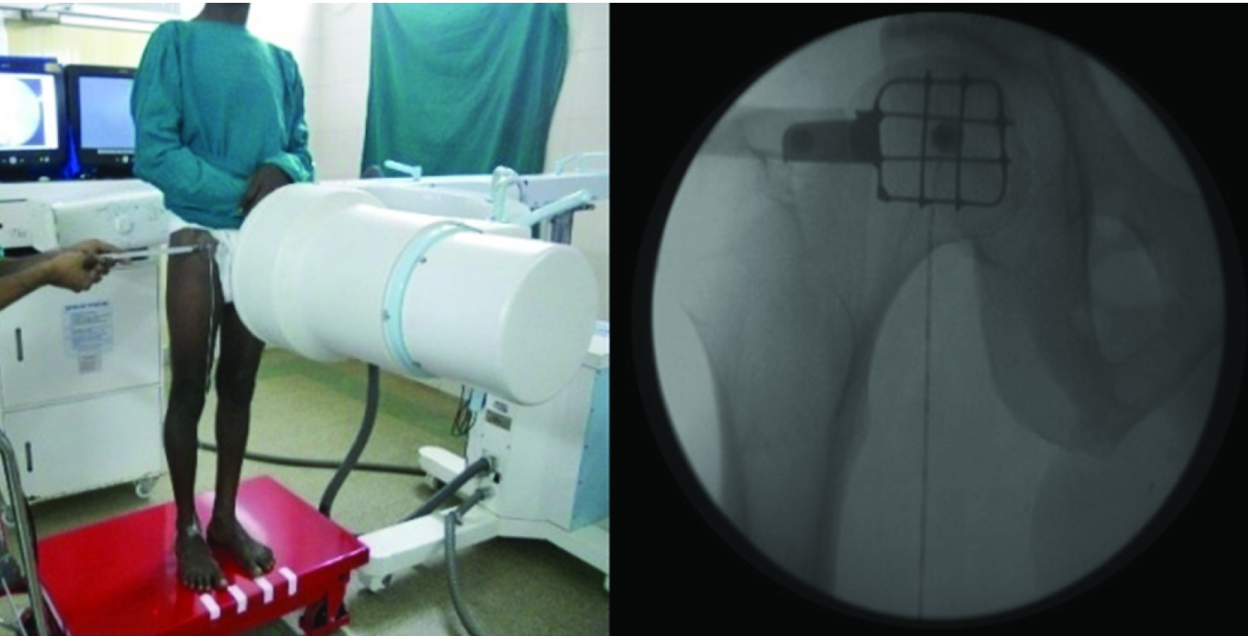
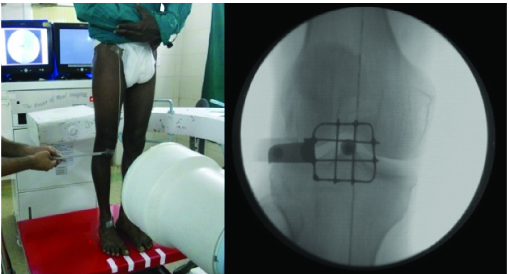
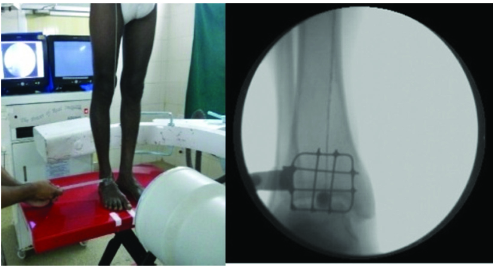
After institutional ethical committee approval, pilot study was conducted using the described technique on 15 patients diagnosed with Primary OA knee (as per the American college of rheumatology criteria) [6] over a period of six months (May 2012 to October 2012) after obtaining requisite consent. Patients selected were in the age group 40 to 70 years. Patients younger than 40 years of age and secondary OA of knee were excluded from this study. The deviation from the mechanical axis was measured in the following manner. A manually operated, hydraulic mechanism based, elevating scissor lift table was used. (Vanjax scissor lifting table. Type: VXLT – 500/880). It is made of high quality steel and is designed for the lifting and transport of heavy loads upto 500 kg. The table or platform size is 815 X 500 X 50 mm. It can lift the patient from a minimum height of 285 mm to a maximum height of 880 mm from ground level. It has a foot pedal, polyurethane wheels, a mechanical lock/wheel break and weighs approximately 80 kg. Patient was asked to stand erect over the elevating lift table with both patellae facing forward and the great toes over the label markers on the rectangular base of the lift table. Patient was instructed to place full and equal weight on both lower extremities, without being assisted by any supporting device. C-arm image intensifier was positioned horizontally. Radiological markers used were metallic buttons with a diameter of 8 mm. They were tied to a custom made radio-opaque cotton thread coated with plaster of paris. One metallic button was placed at the centre of head of the femur and another at the centre of the tibio-talar joint. The radio-opaque thread represents the mechanical axis of the lower limb. A metal mesh was used to guide the exact point of location of the centre of head of the femur and centre of the ankle. This was a custom made metal mesh with an aluminium handle. It has 9 quadrants each of 1 x 1 cm size. Clinically, a point just below and lateral to mid inguinal point was palpated and marked with a pen. The mesh was held horizontally by the handle and placed with central quadrant over the mark. C- arm view was taken and it was confirmed if the centre of the head of femur corresponds with the mark [Table/Fig-2]. If not, the skin over the quadrant which corresponds with the head centre was marked. This method reduces the number of C-arm exposures that might be needed in case of a trial and error method. Similarly, C-arm views of ankle and knee joint were taken to confirm whether the marker corresponds to the centre of the respective joints. This was done by varying the height of the lift table [Table/Fig-3,4]. The deviation from the centre of the knee (mechanical axis deviation in centimeters) was measured by the distance between the marker at the centre of the knee and radio-opaque thread. Medial deviation of the mechanical axis was denoted as varus alignment of the limb and lateral deviation as valgus malalignment. It was recorded and correlated with pain as measured on a Visual Analogue Scale (VAS score – 0 to 10)
Patient standing on scissor lift table with patella and great toe facing forward. Surgeon using metallic mesh with long handle to determine the radiological centre of femoral head and C-arm picture showing centre of the head coinciding with the central quadrant of metallic mesh.
Surgeon using metallic mesh with long handle to determine the radiological centre of knee and its C-arm picture.
Combination of lowering the C-arm and rising the scissor lift would facilitate the surgeon to determine the radiological centre of ankle.
Results
In this study, all the 15 patients had a varus deformity of the knee joint. There was no case of valgus malalignment in the study group. The mechanical axis deviation values were recorded by measuring distance between the centre of the knee and radio-opaque thread in cm. This was measured in each case both clinically and from the image on the monitor with appropriate correction for magnification. The two values were found to be statistically same. The values are shown in [Table/Fig-5]. Pain was measured on VAS. Mechanical axis deviation values and VAS score were found to be positively significantly correlated {p= 0.030 for MAD (right knee) and p= 0.008 for MAD (left knee)} [Table/Fig-5]. More the deviation from the mechanical axis, more was the pain.
Mechanical axis deviation chart.
| S. No. | Patient age in years | MAD (Right) in cm | MAD (left) in cm | VAS† Score (0 – 10) |
|---|
| 1 | 62 | 3.0 cm | 3.5 cm | 5 |
| 2 | 54 | 2.0 cm | 2.2 cm | 3 |
| 3 | 50 | 2.2 cm | 1.5 cm | 3 |
| 4 | 68 | 3.2 cm | 3.5 cm | 4 |
| 5 | 48 | 1.8 cm | 1.5 cm | 2 |
| 6 | 65 | 3.5 cm | 3.3 cm | 3 |
| 7 | 66 | 3.8 cm | 4.2 cm | 6 |
| 8 | 53 | 2.5 cm | 2.8 cm | 4 |
| 9 | 52 | 2.3 cm | 2.2 cm | 1 |
| 10 | 60 | 3.6 cm | 3.5 cm | 4 |
| 11 | 55 | 2.2 cm | 2.5 cm | 3 |
| 12 | 58 | 3.0 cm | 3.0 cm | 4 |
| 13 | 55 | 2.8 cm | 2.5 cm | 3 |
| 14 | 56 | 3.2 cm | 3.5 cm | 2 |
| 15 | 58 | 2.8 cm | 2.5 cm | 2 |
(*MAD – Mechanical axis deviation, †VAS – Visual Analogue Scale).
Discussion
Recreating the normal alignment of the lower extremity is a key factor in any surgical deformity correction of lower limb. Thus there is a need of a reliable means to evaluate lower limb alignment pre- and postoperatively for the management of such patients.
In the current study a method was devised to determine the mechanical axis deviation of lower limb in OA knee patients in a weight bearing position. The axial forces acting across the knee joint are substantially larger during weight bearing as opposed to supine position [8]. In the neutrally aligned knee, the ground reaction forces pass just medial to the joint centre, creating an adduction moment that increases medial compartment forces as compared to lateral side. With increasing varus malalignment, the moment arm for the ground reaction force vector is further increased [9,10]. The knee joint is dependent on the integrity of the soft tissue restraints, including the collateral ligaments, for medial and lateral stability. The lateral collateral ligament complex and the iliotibial band provide the primary soft-tissue restraints to lateral joint opening. Knee joints with varus malalignment and a high adduction moment can thus open up laterally, especially with weight-bearing. Thus methods used in the past which measure MAD in a supine (CT Scanogram) position are not reliable for planning operative interventions, more so in patients who are obese or who have pathological laxity of the knee joint. To the best of our knowledge, to this date there is no method described in English literature which is used to measure the mechanical axis of the lower limb using CT scan in standing position. The existing method of evaluation mechanical axis in standing position involves three [11], two or one [12] long x ray film. Some of the methods have not specified any technical details [13]. There is a lack of unanimity and clarity regarding the distance between the tube and the cassette varying from 80cm [14], 180cm [15], 200cm [16], 300cm [17]. There is also lack of understanding whether multiple x-ray exposure are needed if the number of cassettes used is more than one. There is only one study by Laskin et al., which has given the actual factors(60MAS-76KV) [15].
The authors in this study have described a new and dynamic method of determining mechanical axis deviation with very little variables and margin of error which is also surgeon friendly. The C-arm used for this method emits some radiation but it is substantially low when compared to CT/Plain x rays. Radiation exposure to surrounding staff can be minimized by using conventional lead aprons.
Limitation
Our study had some limitations. Comparison of these findings were not done because of non-availability of obtaining the same using single cassette long film standing x ray. Patients had to be taken to the operation theatre where the image intensifier is available. It was more time consuming. In this study the images were not stored as hard copies because the c-arm that was used did not have the option for printing the images. However, if one wishes to use high end c-arms with printable options the same may be stored as hard copies. This was a pilot study on 15 patients, the study on larger sample size is required to comment on the feasibility.
Conclusion
This method allows for a comprehensive analysis of the magnitude and source of limb malalignment. This technique is dynamic, reproducible and more accurate than other methods for assessing frontal plane deformities of the lower limb in an erect, weight bearing position. It is superior to methods like supine radiographs of knee, CT scanogram, electrocautery cord method (which cannot be done in weight bearing position). This is the only method for quantifying mechanical axis deviation in standing position and is a substitute for full length x ray. But this simple innovative method will be a very handy modality which can be employed in places and institutions where full length cassettes and x rays are not available. It is unique and accurate. It may even be superior to standing full length radiographs of the lower limb since the problem of magnification does not exist with this method. It also avoids excessive radiation to the patient caused during conventional radiography. It may be utilized for planning conservative as well as surgical interventions in patients with severe osteoarthritis of knee. The final aim of any surgical method for correcting deformity of lower limb would be to get a normal MAD. This method can be used to record the amount of surgical correction achieved in a deformed knee by comparing the MAD values pre- and postoperatively.
(*MAD – Mechanical axis deviation, †VAS – Visual Analogue Scale).
[1]. Papaioannou TA, Digas G, Bikos Ch, Karamoulas V, Magnissalis EA, Femoral neck version affects medial femorotibial loadingISRN Orthop 2013 :1-6. [Google Scholar]
[2]. Tetsworth K, Paley D, Malalignment and degenerative arthropathyOrthop Clin North Am 1994 25:367-77. [Google Scholar]
[3]. Cicuttini F, Wluka A, Hankin J, Wang Y, Longitudinal study of the relationship between knee angle and tibiofemoral cartilage volume in subjects with knee osteoarthritisRheumatology (Oxford) 2004 43:321-24. [Google Scholar]
[4]. Brouwer GM, van Tol AW, Bergink AP, Association between valgus and varus alignment and the development and progression of radiographic osteoarthritis of the kneeArthritis Rheum 2007 56:1204-11. [Google Scholar]
[5]. Paley D, Principles of deformity correction 2002 BerlinSpringer:61-97. [Google Scholar]
[6]. Sabharwal S, Zhao C, Assessment of lower limb alignment: supine fluoroscopy compared with a standing full-length radiographJ Bone Joint Surg Am 2008 90:43-51. [Google Scholar]
[7]. van de Pol GJ, Verdonschot N, van Kampen A, The value of the intraoperative clinical mechanical axis measurement in open-wedge valgus high tibial osteotomiesThe Knee 2012 19:933-38. [Google Scholar]
[8]. Felson DT, Epidemiology of hip and knee osteoarthritisEpidemiol Rev 1998 10:1-28. [Google Scholar]
[9]. Andriacchi TP, Dynamics of knee malalignmentOrthop Clin North Am 1994 25:395-403. [Google Scholar]
[10]. Puno RM, Vaughan JJ, Stetten ML, Johnson JR, Long-term effects of tibialangular malunion on the knee and ankle jointsJ Orthop Trauma 1991 5:247-54. [Google Scholar]
[11]. Duparc J, Massare C, Radiological measurement of the angular deviation of the knee in the frontal planeAnn Radiol 1967 1O:635-56. [Google Scholar]
[12]. Petersen TL, Engh GA, Radiographic assessment of the knee alignment aftertotal knee arthroplastyJ Arthroplasty 1988 3:67-72. [Google Scholar]
[13]. Schneider R, Hood RW, Ranawat CS, Radiologic evaluation of kneearthroplastyOrthopClin North Am 1982 13:225-44. [Google Scholar]
[14]. Johnson F, Leitl S, Waugh W, The distribution of load across the knee. A comparison of static and dynamic measurementsJ Bone Joint Surg Br 1980 62:346-49. [Google Scholar]
[15]. Laskin RS, Denham RA, Apley AG, Replacement of the knee 1984 Springer-VerlagHeidelberg:49-107. [Google Scholar]
[16]. Boegard T, Brattstrom H, Lidgren L, Seventy-four Attenborough knee replacements for rheumatoid arthritis: A clinic and radiographic studyActa Orthop Scand 1984 55:166-71. [Google Scholar]
[17]. Freeman MAR, Arthritis of the knee: clinical features and surgical management 1980 Springer-VerlagHeidelberg:1-30. [Google Scholar]