Clinical Tip for Adjusting Reverse Pull Facemask/Headgear Assembly
Sandhya Jain1
1 Professor and Head, Department of Orthodontics and Dentofacial Orthopedics, Government College of Dentistry, Indore, M.P., India.
NAME, ADDRESS, E-MAIL ID OF THE CORRESPONDING AUTHOR: Dr. Sandhya Jain, 125, Shantiniketan Vijay Nagar, Indore-452001, India.
E-mail: researchorthodontics@gmail.com
Point of force application is critical in predicting the result of reverse pull headgear assembly. Different people have suggested different point of force application. A clinical tip is provided for adjusting the hook of intraoral stabilizing appliance, so that it rests on zero moment line which helps in translatory movement of maxilla. Simple and effective clinical method of adjusting the reverse pull headgear is illustrated here along with its biomechanical justification.
Appliances, Center of resistance, Dento-maxillary complex
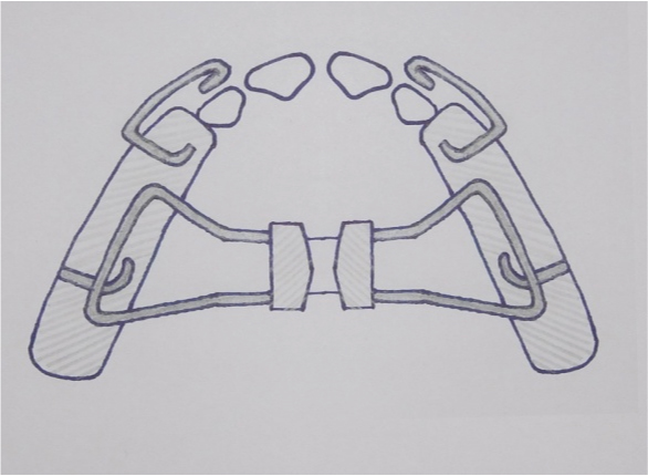
Point of force application is critical in predicting the result or outcome of reverse pull facemask headgear assembly. Delaire [1] used elastics from molars to protract maxilla while Nanda [2] used elastics from facebow to protraction headgear. Facebow was inserted distally in to the buccal tube in first deciduous molar region. Some clinicians use the intraoral stabilization appliance [Table/Fig-1] with a hook in canine area [3] whereas others placed hook in between incisors in the appliance for applying force for protracting maxilla [4,5].
Intraoral stabilization appliance.
Thus, different people have used different designs of appliances with different point of force application getting variable skeletal as well as dental results.
According to Constanti and Legan [6] Zero moment Line of Force is the line of force passing through centre of resistence (CR) causing pure translation. So applying force along Zero moment Line of Force would produce translation of maxilla.
Hence, the first step is to identify centre of resistance of dentofacial complex.
A simple effective clinical method of adjusting the reverse pull headgear is illustrated here with its biomechanical justification:
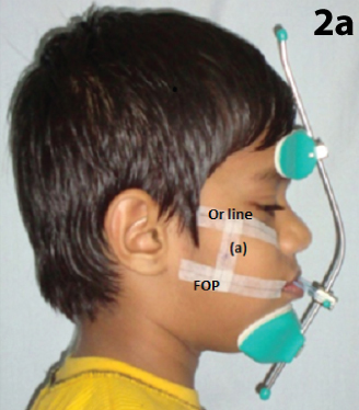
Step I: Determine the center of resistance of dento-maxillary complex [Table/Fig-2]. Ask the patient to bite on a scale in such a way that cheek is pushed out and then draw functional occlusal plane and line through orbitale which is parallel to functional occlusal plane (FOP).
Locating Center of resistance of dentomaxillary complex Center of resistance of dentomaxillary complex lies in between FOP, functional occlusal plane; and (Or) orbitale Line through Orbitale parallel to FOP, (a) perpendicular line passing distal to root of first permanent maxillary molar area.
Showing zero moment line (ZML), centre of resistance (CR).
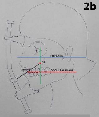
Then draw a vertical line on cheek distal to root of first permanent molar area.
Center of resistance of dentomaxillary complex lies in between (FOP), functional occlusal plane; and Or, orbitale line on the vertical line distal to root of first permanent molar area [7].
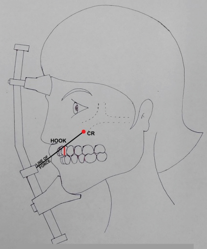
Step II: Adjust the horizontal bar of protraction headgear according to growth pattern of patient and Draw a zero moment line [Table/Fig-3] from center of resistance to horizontal bar of the face mask.
Showing position of hook of intraoral stabilization appliance and line of force (LOF).
1. If we require downward and forward movement of maxilla – adjust horizontal bar little downward direction against lower lip so that zero moment line of force, (line passing through center of resistance of dentomaxillary complex) is 20-40 degree to occlusal plane).
2. If we require only forward movement of maxilla- adjust horizontal bar more superiorly against upper lip (so that zero moment line of force is approximately lesser than 20 degree to occlusal plane).
Step III: Accordingly adjust the length of the hook of the stabilizing appliance so that it rests on zero moment line [Table/Fig-3].
In vertical growers if we adjust the horizontal bar of the protraction head gear as higher as possible so that the point of force application gets closer to CR and the line of force becomes more horizontal. This will help in translatory movement of maxilla in forward direction. The zero moment line passes in between lateral and central incisor, thus hook is positioned between lateral and central incisor as anterior and as superior as possible in high angle cases whereas in low angle cases hook is positioned between primary canine and molar. Thus the position of hook rests on zero moment line.
If the elastics are used from first permanent molars to horizontal bar there would be rotation of occlusal plane anticlockwise because the elastics are used from behind the center of resistance. Dento-alveolar changes (counter clock wise rotation of occlusal plane) will be more.
Conclusion
Thus according to the biomechanics of protration head gear, hook of intra oral appliance should be positioned in canine premolar (or deciduous first molar) area in horizontal growers whereas in vertical growers it is placed more anteriorly and is slightly at higher position.
[1]. Proffit WR, Contemporary orthodontics5th editionElsevier publishers:236 [Google Scholar]
[2]. Nanda R, Biomechanics and Esthetic strategies in clinical orthodontics 2012 2nd edition:337 [Google Scholar]
[3]. Singh G, Textbook of Orthodontics 2007 2nd editionJaypee Publishers:502 [Google Scholar]
[4]. Kharbanda OP, Orthodontics diagnosis management of malocclusion and dentofacial deformities 2009 1st editionElsevier:407 [Google Scholar]
[5]. Turley PK, Orthopedic correction of Class III malocclusion with palatal expansion and custom protraction headgearJ clin Orthod 1988 22(12):314-25. [Google Scholar]
[6]. Contasti GI, Legan HL, Biomechanical guidelines for headgear applicationJ Clin Orthod 1982 16(5):308-12. [Google Scholar]
[7]. Braun S, Extraoral appliances: A twenty-first century updateAm J Orthod Dentofacial Orthop 2004 125:624-29. [Google Scholar]