Introduction
Present day’s busy lifestyle of human race has increased the need of convenience, & Orthodontists are not an exception. Orthodontics being complicated in itself, is further more tangled with the futuristic approach & view of present malocclusion to the corrected condition which has to be achieved. Also, the approach towards diagnosis & treatment planning from the old scenario where the clinician used to decide what best suits the patient, has been changed to a new concept wherein the patient is given choices and allowed to select a plan for oneself [1].
Plaster casts have been in use for the analysis and treatment planning of all orthodontic cases. Though the casts used for these analysis are called as the study casts, much of the study has been merely speculation as to what might be accomplished orthodontically. Later, Kesling [2] had proposed Diagnostic set up taking Tweed’s [3] concept into consideration, which gave a better visualization of the treatment options using the plaster casts of the patients. Also, a carefully executed set up, following his technique aided the operator in making decisions on advisability of elimination of dental units, in simple words planning the extractions [2].
Though the Kesling’s approach was a 3-D futuristic approach, which also disclosed tooth discrepancy, anchorage problems & helped in fabrication of the arch wire forms during treatment [2], but it had many unseen flaws which are as follows:
1. It is time consuming
2. Needs energy and manpower
3. Mesio-distal tooth dimensions and anatomic details are lost while placing vertical cuts
4. Requires a number of armamentarium, etc.
During the case discussions in our institute, we felt the need of visualization for the treatment plan, and for the prediction and visualization of post treatment occlusion after planning for extraction, be it symmetric or asymmetric, we have developed a model which can help us visualize the final occlusion in the matter of seconds.
For better understanding of the concept of the model which we have named as “OCCLUSION CALCULATOR” let us give you a brief description about it.
Material Required
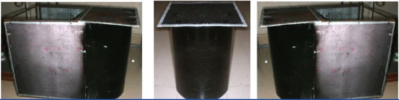
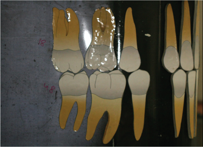
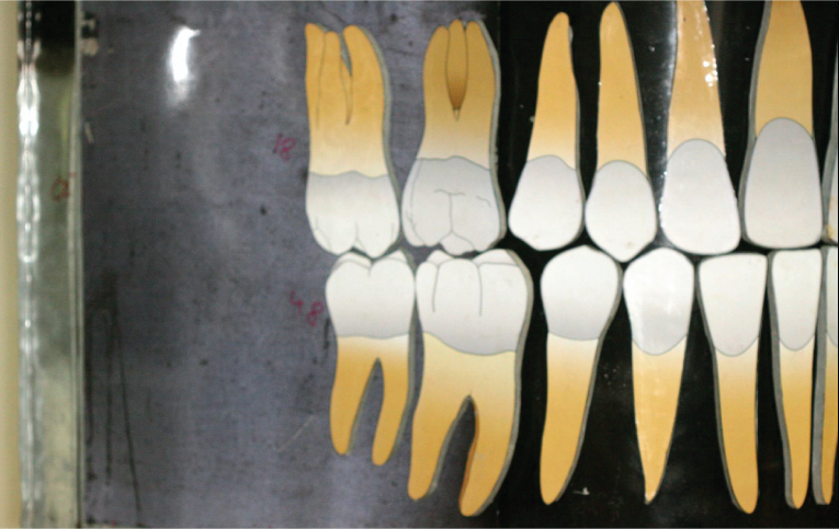
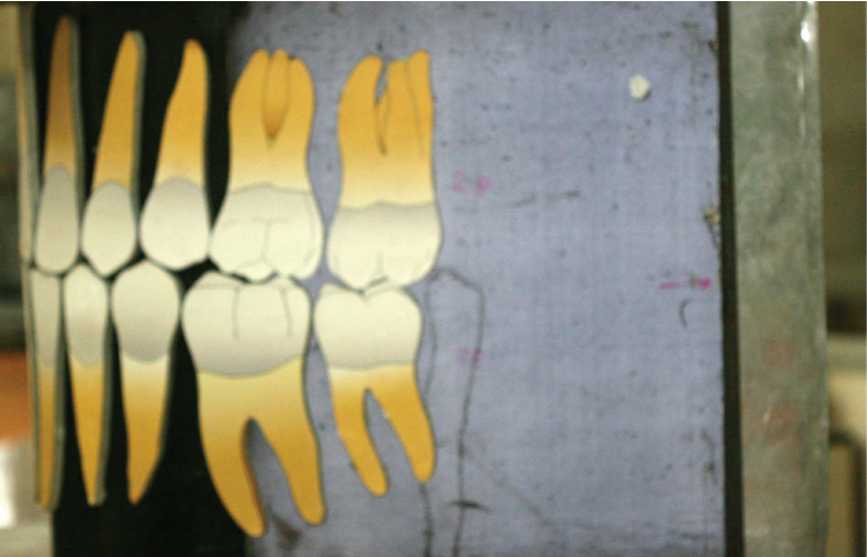
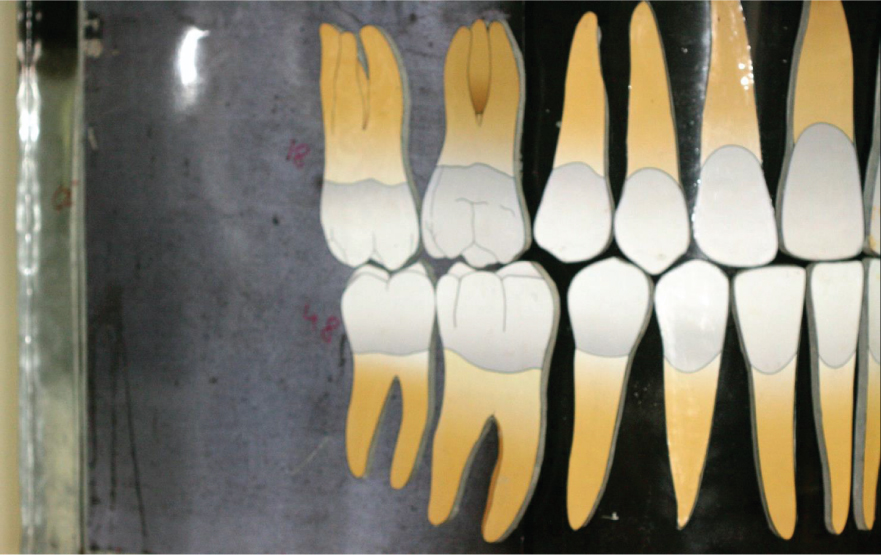
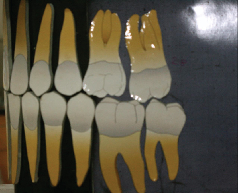
Occlusion calculator, comprises of the tooth replica, and a metal sheet base movable on a sheet holding device and a metal scale (which can be used for measuring the change in arch length) [Table/Fig-1,2].
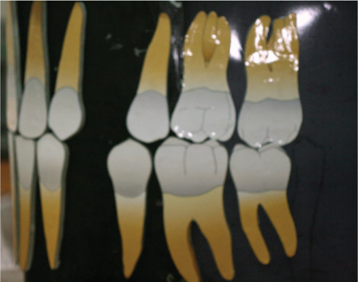
1. Tooth replica: These are the magnified replica of the anatomic details of the teeth presented in Wheelers. The teeth are of the size magnified in dimensions to the power of ten to the dimensions that in Wheelers. These replicas are prepared with any easily available material with a thickness of more than 10 mm. which aids in easy handling, durability, and resistance to distortion. As the teeth are prepared, they are colored, and magnet is attached onto its back, which aids in attachment to the metal sheet.
2. Metal sheet: A Galvanized metal sheet (GI sheet) of the dimensions 2 ft x 6 ft is required for the attachment of teeth on the sheet for presentation. This sheet is rigid vertically and flexible horizontally so that can be rolled as and when required. Marking are made on the sheet for the midlines & the canine relation line.
3. Sheet holding device: It’s a metal framework, with slots for the passage of the metal sheet. It gives the structure to the arch form and also mode of movement of sheet on it. The posterior segment is stable which carries the molars on the either side. The metal sheet which can slide, passes behind the molar sheets which masks the metal sheet.
Procedure
For using the occlusal calculator, assumptions are made that the arches will be aligned orthodontically before starting the retractions. This space can either be present before the treatment or could be the extraction spaces. Therefore, to begin with the calculation, the personnel has to arrange the tooth models in an aligned archform irrespective of the space needed because if the space left over after alignment is less that means the extraction will be required and the space obtained by extraction is used for aligning the teeth in levelling and alignment phase of orthodontic treatment. Therefore the alignment of the arches has to be done with midlines matching and tooth properly levelled and aligned. This is a hypothetical step (similar to that done in Kesling’s Diagnostic set up), as we have to see the results and accordingly decide whether to extract the teeth or not, thereby the Andrews six keys are always kept in mind and accordingly the teeth are arranged. This can be done with the help of magnets stuck to the back of the tooth replica, which sticks to the iron sheet. In case of proclination of the anteriors, an assumption need to be made of the overjet because it cannot be produced on the calculator as it is a two dimensional model. Thus the space could be assumed to be required for retraction and then molar relation is calculated using the Occlusion Calculator. In cases of tooth size discrepancies, the tooth are considered for prosthetic build ups, which will be simulated by the normal sized tooth used in the occlusion calculator.
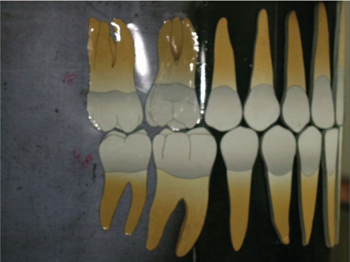
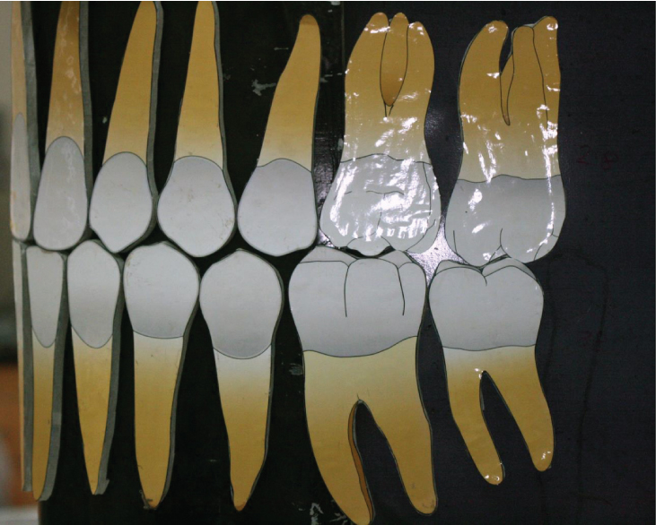
The teeth are arranged in the regular fashion. The malocclusion present in the case can be simulated on the model after alignment but keeping the molar relation same as that in the case (e.g. Class I Malocclusion with Bimaxillary Protrusion, [Table/Fig-2-4]). The planned extraction can be executed on the model (e.g. All 1st Premolar Extraction [Table/Fig-5,6,7]), and the remaining teeth are arranged keeping the incisors midlines, canine relation and the molar relations constant. The space remaining after the arrangement of teeth can be closed by sliding the metal sheet from the posterior side, thereby representing retraction of the teeth [Table/Fig-8,9,10], which can be measured on the metal scale placed in front.
Another example with little increased difficulty is as follows, if we extract only Upper premolar and lower left 1st premolar in Class II Division 1 subdivision left malocclusion, then the Occlusion would be? The answer for it is, we could finish the case with Class I molar relation on right side and Class II molar relation on the left side, with Class I canine relation bilaterally and a proper 2 mm of overjet and overbite [Table/Fig-11,12,13]. To explain this, keep a rule in the mind, which is as follows: The side where both upper and lower premolar is extracted, it will be ending into Class I molar and canine relationship. Whereas if only upper premolar is extracted then the molar relationship will be class II and canine relation will be Class I. This is a rule of thumb, and the occlusion calculator is made with the idea of explaining this rule of thumb. Once the beginner uses this calculator, he/she will understand this concept well.
Therefore, using Occlusion calculator, various malocclusion present in the case could be simulated and various treatment plans for the case could be mimicked to visualize the resultant tooth relationship and occlusion relationship. Therefore, the best resultant treatment plan could be finalized in just a fraction of seconds. It also helps the clinicians and PG students to visualize the resultant of their plans, anchorage requirements and other biomechanical aspects which builds a discussion forum for the case, and finally help them to frame the best plan for the case.
Uses And Applications
1. During the case discussions in the orthodontics post graduate curriculum.
2. Helps in planning the treatment in clinics and hospitals.
3. To explain the resultant of the treatment to the patients, thus it helps in patient motivation.
4. It is a learning aid for general dentists, which builds up a concept about extractions in orthodontics.
Advantages
1. User friendly: Easy to use.
2. Less time consuming: Resultant occlusion can be visualized in just a fraction of second.
3. Easy to master the technique
4. Aids in building up the concepts in treatment planning, anchorage and biomechanics considerations,thus helps in visualization of the flaws, so that it can be rectified, before the execution of the treatment
5. Cost effective: Every institute can afford to have one.
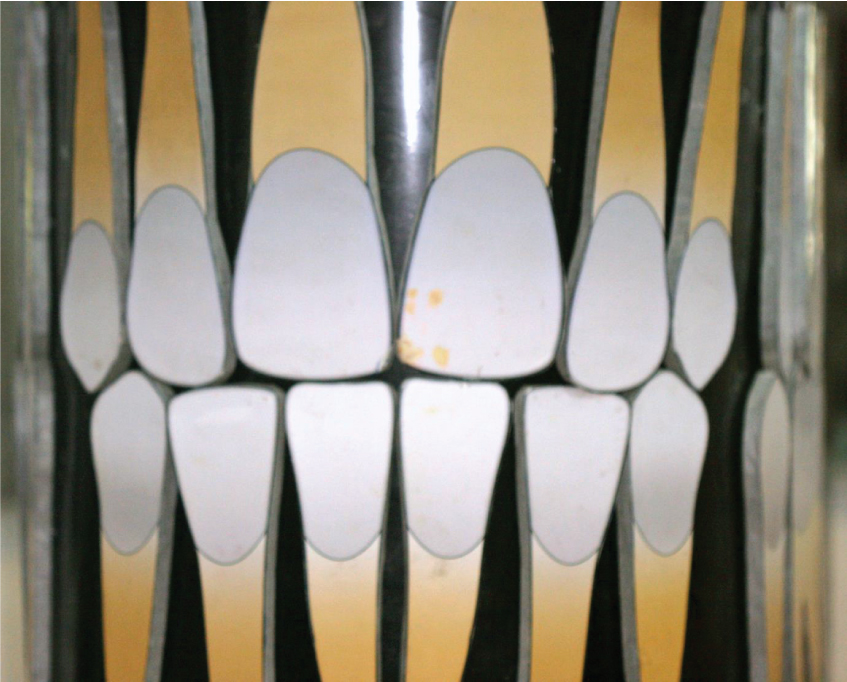
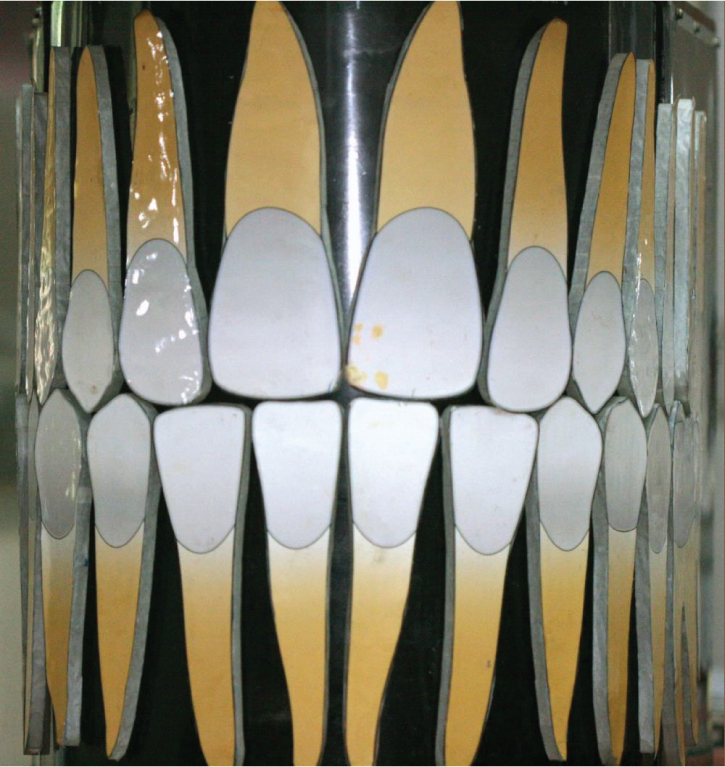
Structure of occlusion calculator (frontal, right and left lateral views)
Class I bimaxillary protrusion (frontal View),
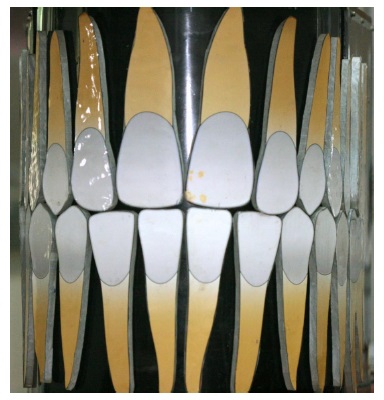
Class I bimaxillary protrusion (right lateral view),
Class I bimaxillary protrusion (left lateral view)
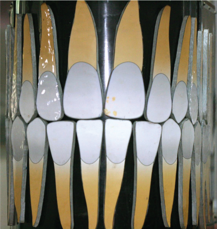
Class I bimaxillary protrusion with all 1st premolar extracted (frontal view),
Class I bimaxillary protrusion with all 1st premolar extracted (right lateral view)
Class I bimaxillary protrusion with all 1st premolar extracted (left lateral view)
Class I bimaxillary protrusion corrected after retraction and space closure (frontal view),
Class I bimaxillary protrusion corrected after retraction and space closure (Right lateral view),
Class I bimaxillary protrusion corrected after retraction and space closure (left lateral view)
Class II Division 1 subdivision left malocclusion corrected after retraction and space closure after extraction of 14, 24 and 34 having Class I canine relation bilaterally and Class I molar relation at left side and Class II molar relation at right side (frontal view)
Class II Division 1 subdivision left malocclusion corrected after retraction and space closure after extraction of 14, 24 and 34 having Class I canine relation and Class II molar relation at right side (right lateral view)
Class II Division 1 subdivision left malocclusion corrected after retraction and space closure after extraction of 14, 24 and 34 having Class I canine relation and Class I molar relation at left side (left lateral view)
Limitations
Not all type of malocclusions and tooth movements (e.g. Tooth size discrepancy, transverse problems, etc) can be simulated as it is a two dimensional model of a three dimensional entity.
Conclusion
Thus, the treatment planning is made easy, more realistic, futuristic, visualistic, which will be a supplement to the presently available diagnostic aids. Though, this model is primarily intended for the orthodontic post graduate teaching, it can also be of considerable use even to the seasoned orthodontist. The regular use of “ORTHODONTIC CALCULATOR” in our department is the testimony of its usefulness.