The implant’s diameter is important to ensure sufficient bone to implant contact. However, it should be pointed out that a minimum of 1mm of bone thickness must surround the entire implant surface. Based on their diameter, the implants can be classified as follow: (< 3 mm), narrow (< 3.75mm), standard (< 4mm) or wide (> 4mm)[1-4].
Narrow-diameter implants (< 3.75mm) are indicated in cases of alveolar bone loss prior to tooth extraction as a result of period–ontal disease, periapical pathology, or trauma to teeth and bone. Additionally, damage of the bone tissues after traumatic tooth extractions or late implantation (bone atrophy) may exhibit an insufficient implantation bed for regular sized implants [1-7].
Nevertheless, it has been shown that implants with wider diameters reduce the maximum stress values in the bone, are mechanically more resistant and the removal torque values are reported to be higher when compared to narrow-diameter [8-11].
Nevertheless, further studies are warranted to clarify the bio–mechanical behavior of narrow-diameter implants in several clinical situations. In addition, there is a lack of consensus among authors regarding the viability and success rates of using these implants in oral rehabilitation. Also, the study of the biomechanical behavior of these implants is scarce and divergent mainly about their use in posterior area.
Therefore, the current study investigated the biomechanical behavior of screwed partial fixed prosthesis supported by implants with different diameters (mini, narrow and standard) with single and splinted 3-piece unit crowns by using a photoelastic analysis. It was hypothesized that the stresses on the models are inversely proportional to the increase of implant diameter.
Materials and Methods
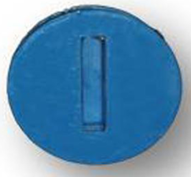
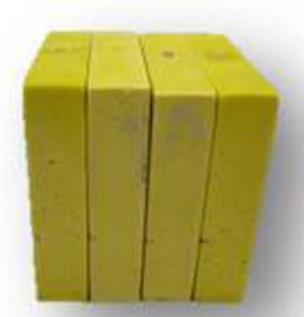
A metallic matrix (40x45x10 mm) was fabricated and poured with silicone (Sapeca artesanato, Bauru, São Paulo, Brazil) [Table/Fig-1]. The space provided by the matrix was filled out with type IV dental stone (Durone, Dentsply, Petrópolis, Rio de Janeiro, Brazil) in order to obtain six models [Table/Fig-2]. Models were divided into four groups of six each according to implant diameter and prosthesis as shown in [Table/Fig-3].
Models with type IV dental stone
| Models | Implant | Implant-abutment connection | Diameter | Prosthesis |
|---|
| I | Osteofit | External hexagon | 13x3,75 mm | Single |
| II | Osteofit | External hexagon | 13x3,75mm | 3-unit piece |
| III | Osteofit | External hexagon | 13x3,3 mm | Single |
| IV | Osteofit | External hexagon | 13x3,3 mm | 3-unit piece |
| V | Osteofit | External hexagon | 13x2,5 mm | Single |
| VI | Osteofit | External hexagon | 13x2,5 mm | 3-unit piece |
The models in dental stone were perforated to receive the implant replica (Osteofit, Campo Largo, Paraná, Brazil) of each group. The insertion of the implant replicas was standardized by means a parallelometer (in its long axis). The implant replica was screwed to the corresponding pick-up transfer (Osteofit, Campo Largo, Paraná, Brazil) and inserted into the dental stone block until the platform of the implant replica was in the same level of the upper part of the block. All implant replicas were placed with their long axis perpendicular to the horizontal plane and fixed with self-polymerised acrylic resin (Duralay, Duralay Reliance Dental, MFG Co Worth, IC, USA).
The dental stone models with the implant replicas in place were duplicated and a new mold was obtained in which the according to implant diameter (Osteofit, Campo Largo, Paraná, Brazil) were placed according to each group. Afterwards, the mold was poured with photoelastic resin (PL-2, Vishay, Micro-Measurements Group, Inc Raleigh, NC USA) according to manufacturer’s recommendation. Each set was placed under a pressure of 40 lbf/pol2 to remove internal bubbles, and a total of six models were obtained (models I, II, III, IV, V and VI).
For models I, III and IV, single-unit screwed crowns corresponding to the mandibular second premolar were fabricated. For models II, IV and VI 3-unit screwed crowns corresponding to the mandibular second premolar, first molar and second molar were fabricated. All crowns were fabricated in Nickel-Chromium alloy (Fit Cast –SB Plus, Talladium do Brasil, Curitiba, PR, Brazil) with standardised dimensions. The crowns were screwed in the implants with a torque of 20 N according to the manufacture’s recommendation.
The set was positioned in a circular polariscope and initial photograph record without load application was performed in order to verify the absence of stress on the photoelastic models. Sequentially, 100-N axial and oblique (45 degrees) loads were applied on standardised area of the occlusal surface of all crowns individually during 10s by means of a universal testing machine (EMIC-DL 3000, São José dos Pinhais, Paraná, Brazil). A 45-degree tilted apparatus was used during oblique loading application [15].
Data were photographically recorded (Nikon D80, Nikon Corp, Japan) and further analysed in an image software (Adobe Photoshop CS3, San Jose, California, USA).
Photograph records of all models were qualitatively analysed to verify the direction and intensity of stress. In this sense, the higher the fringes order (N) and fringes number are, the greater the stress intensity. Additionally, the closer the fringes are among each other, the higher the stress concentration [15].
The analysis was divided according to the number of fringes with high intensity (green-pink transition) and to the stress distribution area. All images were evaluated by the same person.
Results
According to the Number of High-intensity Fringes
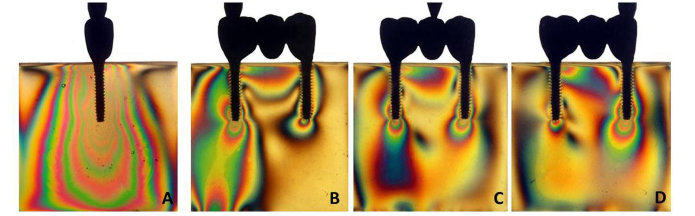
Under axial loading [Table/Fig-4, 5a, 6a, 7a], the number of fringes was inversely proportional to the implant diameter for single unit prosthesis. In order words, the models I (3), III (6) and V (9) showed an increase of stress values. In relation to the splinted prosthesis [Table/Fig-5b-d, 6b-d, 7b-d], the model II [Table/Fig-5b-d] exhibited the lower number of fringes regardless of the loading area application. Models IV and VI displayed the same number of fringes even under different implant diameters. Under oblique loading, a slight increase of fringes number was noted for all groups.
Number of photoelastic fringes according to the crowns in which the load was applied
| Models | Axial loading | Oblique loading |
|---|
| Element | Element |
|---|
| 34 | 35 | 36 | 34 | 35 | 36 |
| I | | 3 | | | 5 | |
| II | 2 | 0 | 2 | 3 | 2 | 2 |
| III | | 6 | | | 8 | |
| IV | 3 | 4 | 4 | 4 | 4 | 4 |
| V | | 9 | | | 10 | |
| VI | 3 | 4 | 4 | 4 | 4 | 5 |
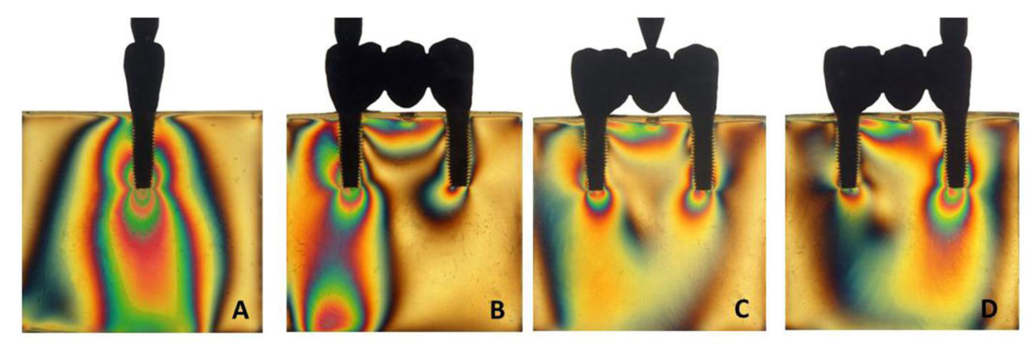
Axial load for models I (A) and II (B,C,D)
Axial load for models III (A) and IV (B,C,D)
Axial load for models V (A) and VI (B,C,D)
According to the Area Distribution of Fringes
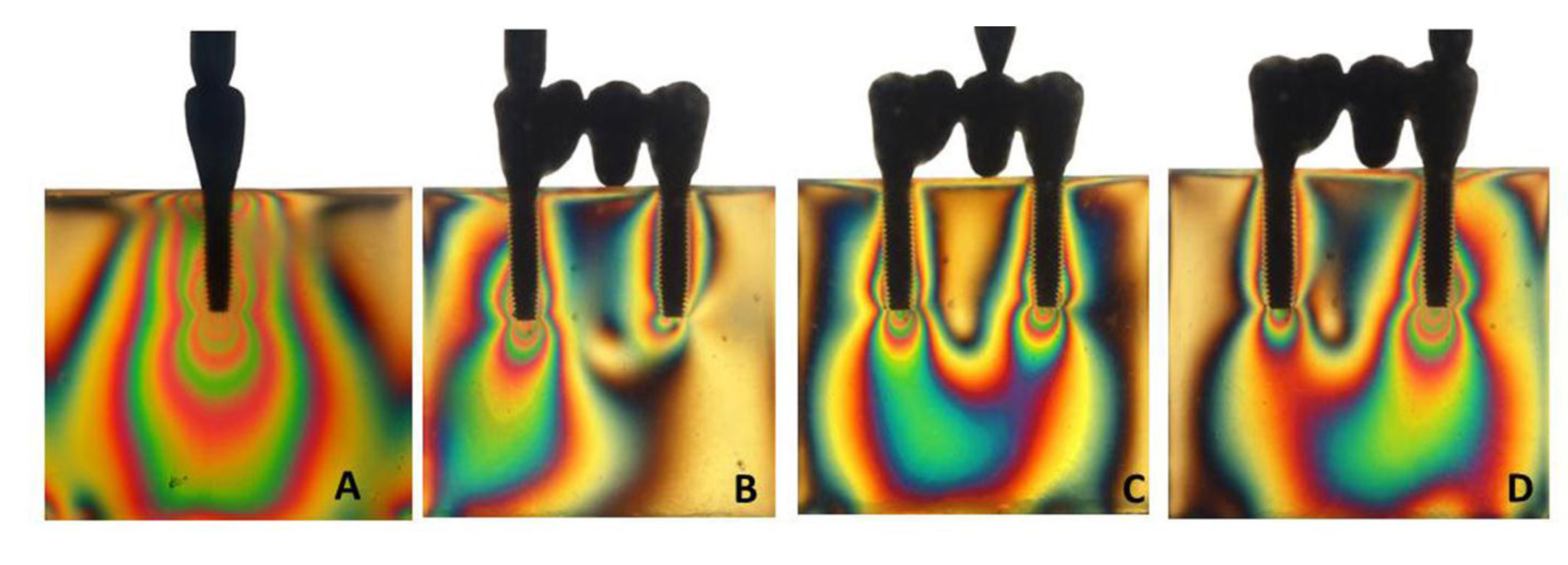
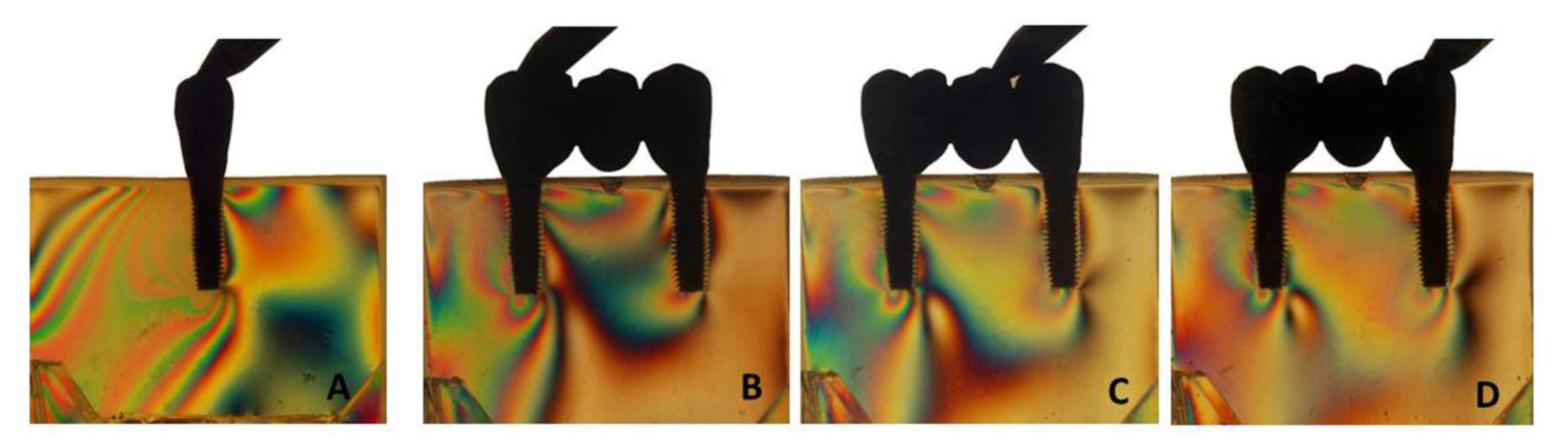
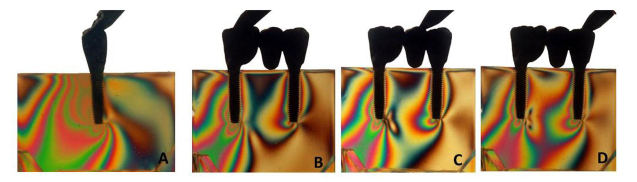
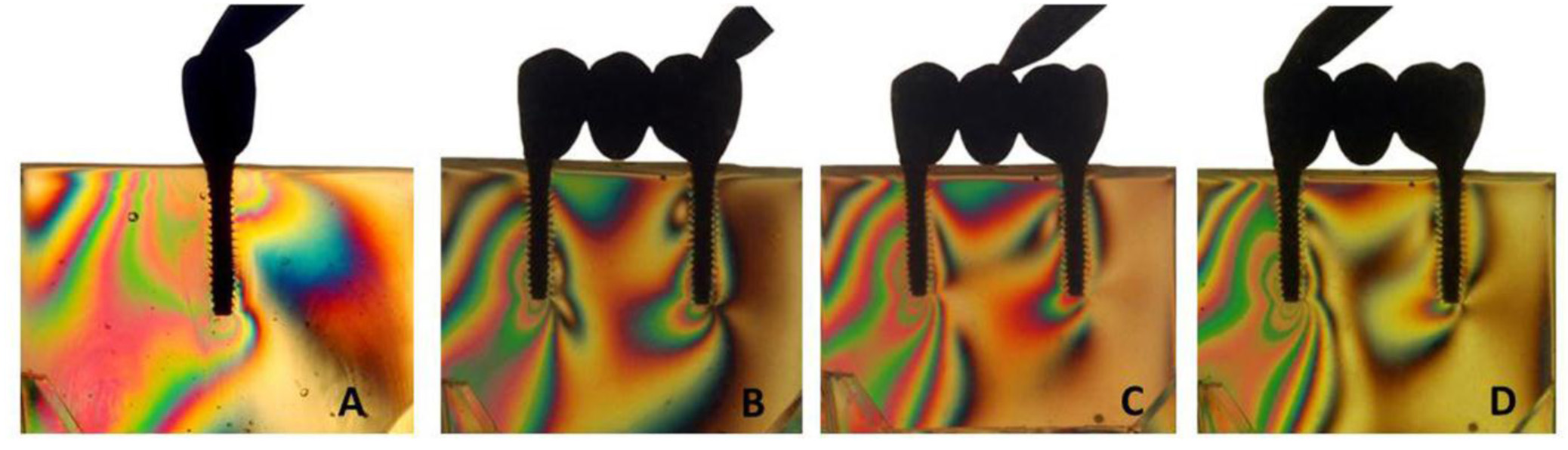
Under axial loading, the stress concentrated at the apex of the implants for all models. Stress concentration of the peri-implant area was observed for models III and V [Table/Fig-5a, 8a, 9a]. Under oblique loading, the stress was mostly located on the implant apex for all models [Table/Fig-10a-d, 8a-d,9a-d]. Models I, III and V [Table/Fig-10a, 8a,9a] also displayed stress concentration on the cervical region of the ipsilateral implant.
Oblique load for models III (A) and IV (B,C,D)
Oblique load for models V (A) and VI (B,C,D)
Oblique load for models I (A) and II (B,C,D)
Discussion
The research hypothesis that the stress on the models would be inversely proportional to the increase of implant diameter was accepted. The mini-diameter implants (2.5 mm) displayed the highest stress intensity followed by narrow (3.3 mm) and standard (3.75 mm) diameter implants.
The load transmission may influence the longevity of implant-supported restorations since the success of osseointegrated implants is directly related to their integration with the surrounding bone [13]. Nowadays, the biomechanical aspects of implant treatments have been emphasised in order to provide the “safe” limits of load transmission to dental implants [16].
Besides achieving implant osseointegration, there is a great concern about the longevity of those implants inserted in unfavorable areas. A specially-designed implant is used in areas with soft and hard tissues defects. For this reason, the industry has been manufacturing implants with different designs and configurations so that the clinician has a broad option to choose the best implant for each clinical situation [17]. Narrow-diameter implants can be used in several adverse conditions such as in cases of alveolar bone loss prior to tooth extraction as a result of periodontal disease, periapical pathology, or dental and bone; damage of the bone tissues during traumatic tooth extractions or late implantation which cause bone atrophy of the edentulous areas [1-7].
Herein, for single crown models the 2.5-mm diameter implant displayed the greatest number of high-intensity fringes followed by the 3.3-mm and 3.75-mm diameter implants [Table/Fig-4]. Similar results were noted by Petrie and Williams [12] who evaluated the influence of diameter, length and taper of dental implants on strains in the two types of bone by using a three-dimensional finite element analysis. Increasing implant diameter resulted in as much as a 3.5-fold reduction in bone strain.
The mini-diameter implants were specifically designed for cases with limited inter-occlusal space, to replace mandibular incisive and maxillary lateral incisive, and when the the buccolingual width of the edentulous ridge is insufficient to place conventional implants and in areas with weak occlusal forces [5,6].
Besides these limitations, the longevity of such mini- and narrow-diameter implants has been proved by several clinical studies [1-4, 18-20] in which the survival rate of these implants are similar to those observed with standard-diameter implants. Recently, Geckili et al.,[1] showed the overall implant success rate after 5y of loading time (98.74%) indicating that narrow implants can be successfully used to support fixed or removable prosthesis.
However, the use of narrow-diameter implants to support restorations should be cautiously evaluated owing to their mechanical strength, reduced bone-implant contact surface, and increased risk of fatigue fracture under clinical loading conditions [8-11].
The relative disadvantages of the narrow implants are weakness from its small diameter, limited contact area between the bone and the implant, and limited prosthetic options. Implants with a 2mm diameter have a fracture strength that is 16 times lower than that of 4mm implants. When the diameter is 1mm, the contact area between the bone and the implant is decreased by 40%. Therefore, narrow implants are not recommended for posterior edentulous areas with high occlusal force 25 [21].
In addition, concerns may arise from the fact that reduced dia–meter means a reduction in the contact surface between the implant and the bone, and one might ask if, in this condition, osseointegration is enough to withstand the loading forces [6,8,10]. Decreasing the diameter also means increasing the risk for implant fracture due to reduced mechanical stability and increased risk of overload [5,11,12].
Under oblique loading, all models exhibited an increase number of fringes [Table/Fig-4] and greater stress concentration mainly at the apex and cervical regions of the ipsilateral implants (models I, III and V; [Table/Fig-8a,9a,10a]). It might be explained by the implant angulation that generates greater lever arm during loading application and promote higher torque around the implant [19].
It is also known that oblique forces are generated at the cervical portion of implants [22,23] which can more easily lead to bone resorption and component fracture [24], reported that the peri-implant bone loss is related to the stress concentration in this area. According to Canay et al., [25], oblique forces result in compressive stress at the bone crest, which is five times greater than the stress induced by axially-loaded implants.
In relation to the splinted 3-unit crowns [Table/Fig-5b-d,6b-d,7b-d], the model II [Table/Fig-5b-d] exhibited the lowest number of fringes regardless of the loading application area. Models IV and VI showed similar numbers of fringes for both implant diameters. The slight difference among groups II, IV and VI may be due to the splinting of crowns.
It is in agreement with Guichet et al., [26] who reported in a photoelastic study that splinted restorations shared the occlusal loads and distributed the stresses more evenly between the implants when eccentric force was applied. And splinting the adjacent prosthetic crowns was also used to decrease peak stresses by load sharing. Additionally, according to the authors implant-supported restorations are splinted primarily to promote better distribution of occlusal forces. Implant-supported fixed partial dentures are splinted to foster the distribution of occlusal forces and to prevent the transfer of detrimental force levels to the supporting implants, which may lead to bone resorption and component failures.
An additional rationale of splinting implant crowns is to favorably distribute the nonaxial loads, minimise their transfer to restoration and the supporting bone and to increase the total load area [27].
Due to the limitations of the present study, it was not possible to determine the level of clinical acceptable stress. However, it is believed that single crowns with greater diameter allow better stress distribution as observed herein. Narrow-diameter implants should be cautiously indicated mainly at areas with high masticatory effort.
Conclusion
The use of standard diameter implants improved the stress distribution when compared to narrow and mini diameter implants. Furthermore, splinted crowns presented a more uniform stress distribution than single crowns. Finally, oblique loading displayed greater stress concentration and intensity than axial loading for all groups.