A Simple 2D Accurate Mini Implant Positioning Guide
Arun Kumar Dasari1, Sushma Parimi2, Kishore M.S.V3, Nagam Reddy Shashidhar4, Sathu Reddy Dharmender5
1Senior Lecturer, Department of Orthodontics, Svs Institute of Dental Sciences, Mahabubnagar, Telangana, India.
2Senior Lecturer, Department of Oral Medicine and Radiology, Svs Institute of Dental Sciences, Mahabubnagar, Telangana, India.
3Professor, Department of Orthodontics, Svs Institute of Dental Sciences, Mahabubnagar, Telangana, India.
4Professor, Department of Orthodontics, Svs Institute of Dental Sciences, Mahabubnagar, Telangana, India.
5Reader, Department of Orthodontics, Svs Institute of Dental Sciences, Mahabubnagar, Telangana, India.
NAME, ADDRESS, E-MAIL ID OF THE CORRESPONDING AUTHOR: Dr. Arun Kumar Dasari, Senior Lecturer, Department of Orthodontics, Svs Institute of Dental Sciences, Mahabubnagar, Telangana, India.
Phone: +919885149654,
E-mail: dr.dasari.arun@gmail.com
One of the major issues in orthodontic treatment is anchorage planning when using a pre adjusted edgewise appliance system. The conventional methods described in the literature include banding of second molars, transpalatal arches and headgears that involve additional teeth or wire components. With the introduction of temporary anchorage devices, anchorage can be ideally planned to treat a case successfully. However, the stability and placement of these mini implants demands accurate positioning, good bone thickness without damaging the adjacent structures. Here, we illustrate a very economical and two dimensional mini implant guide for accurate and easy placement.
Anchorage, Iopa, Mini Implants
Introduction
Advancements in the field of orthodontics have paved way to new possibilities to treat our patients fast and comfortably. Introduction of mini implants in orthodontics has helped us treat many complex malocclusions without orthognathic surgical intervention [1]. However, there was an initial lag in the usage of these mini implants due to operator sensitivity, lack of confidence and accurate positioning methods[2]. The success of implant placement and stability demands good bone thickness either in the labial or palatal regions [3]. Subsequently innumerous methods have been described in the literature. Over a few years 3D technology has totally erased the complicatedness of implant positioning with one major limitation in terms of cost effectiveness [4,5]. Therefore, a simple, economical and reliable chair side procedure has been described below;
The requirements for the following procedure includes,
• Intraoral periapical radiographs
• IOPA grid
• LCP Film holder
• Michigan’s periodontal probe
• Graduated Scale
• OHP marker
• Mini implants with driver
Indications
• High posterior anchorage requirements in the buccal corridor
• Maxillary and mandibular anterior and posterior regions
• Intrusion mechanics in the anterior region
• Intermaxillary distalisation
• Mesialisation of posterior segments
Contraindications
• Placement of implants in the midline or palatal region
• Cases with short vestibular depth
• Cases with reduced attached gingiva
Guide Assessment and implantation Procedure
An intra oral periapical radiograph is made by long cone paralleling technique using a LCP film holder. The paralleling cone technique is mandatory since it eliminates all elongation and magnification errors and gives a precise replica of the teeth and supporting structures in a 1:1 ratio. This radiograph will help us in evaluating inter dental bone support between the molars and the premolars or any other teeth where the implant needs to be inserted.
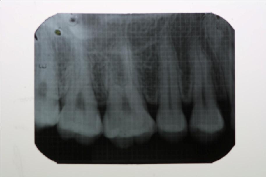
An intraoral periapical grid film is obtained from the Department of Oral Medicine and Radiology. The grid film measures exactly the size of the IOPA (4 x 3 cm) and is made up of two strands of lead (thicker and thinner) incorporated both vertically and horizontally throughout its measurement. The thicker strands are incorporated exactly at 5mm distance both vertically and horizontally, while the thinner strands are built in between the thicker strands precisely at a distance of 1mm. A second IOPA radiograph is taken along with the grid using the same paralleling cone technique. An IOPA radiograph with grid lines superimposed on it is thus obtained [Table/Fig-1].
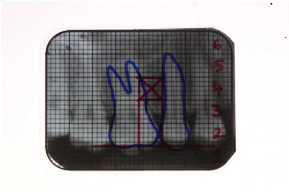
The grid is then superimposed on to the radiograph accurately matching the thick and thin radio-opaque lines. The precise outlines of the teeth are drawn on to the grid using an OHP marker. At one end of the grid mark each box at a distance of 5mm which is easily represented by thick radio-opaque line and number it accordingly. This will accurately guide the height of the implant placement. As shown in the figure the mini implant can be inserted at box 4 [Table/Fig-2].
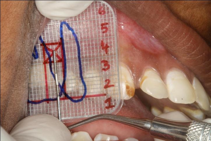
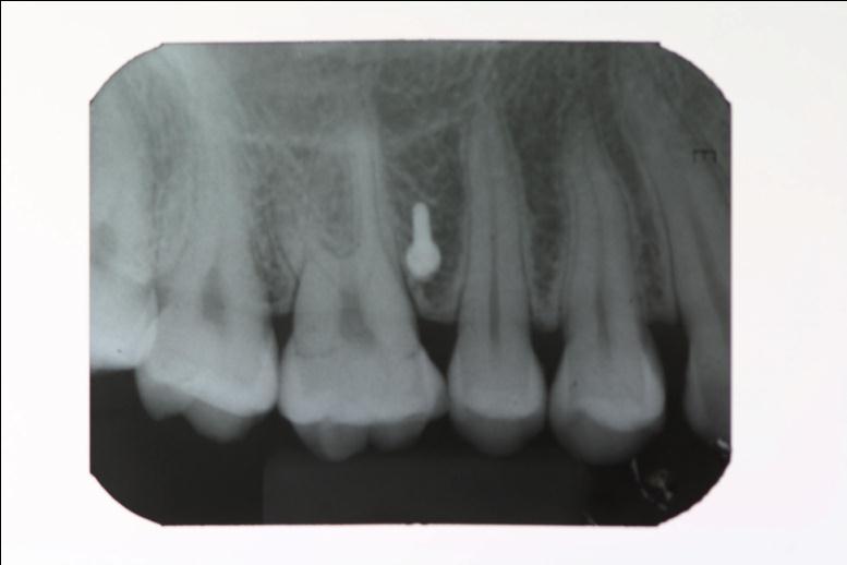
Transfer the grid into the patient’s oral cavity by superimposing on the mesiodistal outlines of molar and premolar. The method is very easy since the grid being flexible and the obtained image would be in 1:1 ratio. Using the Michigan’s probe, the exact height of the implant placement is determined by measuring from the contact point between molar and premolar [Table/Fig-3]. Now transfer this vertical height along the contact point clinically and mark the point of implant placement in the patient’s vestibule. The implant is placed at this point and procedure is completed. This can be confirmed by taking an IOPA using LCP technique [Table/Fig-4]. The IOPA grid can be reused, any number of times after sterilization.
Advantages
• Grid can be sterilized and used any number of times
• It is very reliable and accurate
• Economical and cost effective to the patient
• Saves lot of chair side time
• Minimal radiation
Disadvantages
• It is a representation of 3D image and a 2D technique
• Does not evaluate the bone thickness and density
• Cannot be used for palatal implant placement
IOPA Radiograph with superimposed grid taken in paralleling cone technique
Teeth outline drawn on grid using OHP marker with horizontal (occlusal) and vertical two lines with horizontal lines between 5mm mini implant inserted at box 4
Grid superimposed on mesiodistal outline of molar and premolar, Michigan’s probe to locate the exact height of the implant placement
IOPA radiograph after mini implant placement
[1]. HM Kyung, HS Park, SM Bae, JH Sung, IB Kim, Development of orthodontic micro-implants for intraoral anchorage.J Clin Orthod. 2003 37:321-28. [Google Scholar]
[2]. HS Park, SH Jeong, OW Kwon, Factors affecting the clinical success of screw implants used as orthodontic anchorage.Am J Orthod Dentofacial Orthop. 2006 130:18-25. [Google Scholar]
[3]. HS Park, YJ Lee, SH Jeong, TG Kwon, Density of the alveolar and basal bones of the maxilla and the mandible.Am J Orthod Dentofacial Orthop. 2008 133:30-7. [Google Scholar]
[4]. Sharma Narendra S, Shrivastav Sunita S, Hazarey Pushpa V , RH Kamble, Sharma Preethi N, Universal wire grid for implant placement in three dimensions.World J Dent. 2013 4(1):74-6. [Google Scholar]
[5]. Kim Seong-Hun, Choi Yong-Suk, Hwang Eui-Hwan, Chung Kyu-Rhim, Kook Yoon-Ah, Nelson Gerald, Surgical positioning of orthodontic miniimplants with guides fabricated on models replicated with cone-beam computed tomography.Am J Orthod Dentofacial Orthop. 2007 131:s82-9. [Google Scholar]