Case Report
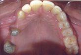
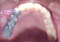
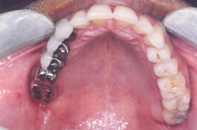
A 39-year-old male patient was reported to the Department of Prosthodontics of MIDSR Dental College and Hospital Latur, India with a chief complaint of dislodged prosthesis, difficulty in mastication as well as aesthetic problem [Table/Fig-1] . Past medical history was in significant and past dental history revealed that patient had undergone extraction of the badly carious right maxillary first premolar and first molar two years back, followed by conventional five unit FPD with rigid connectors, this FPD dislodged several times in span of two years. On Intraoral examination revealed missing right maxillary first premolar and maxillary first molar with right maxillary canine and right maxillary second molar acting as terminal abutments and second premolar act as a pier abutment. Silver amalgam filling seen with maxillary right second premolar and maxillary second molar [Table/Fig-2].On radiographic evaluation the abutment teeth had adequate bone support to be used as abutment.
After discussing all the treatment options and their pros and cons, it was decided to rehabilitate the case with five unit FPD using non-rigid connectors on the distal aspect of a pier abutment. Its risks and benefits were explained to patient and a written, informed consent was obtained.
Clinical Procedure
The following clinical step by step procedure was carried out for his oral rehabilitation,
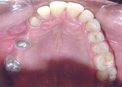
• Tooth preparation was modified for porcelain fused to metal prosthesis on right maxillary canine and maxillary second premolar with equigingival margins and shoulder finish line in order to enhance the aesthetics [Table/Fig-3] .
• Tooth preparation was modified for full metal coverage was done on right maxillary second molar with supragingival margin and chamfer finish line [Table/Fig-3].
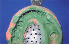
• The gingival retraction was carried out with gingival retraction cord and final impression were made using elastomeric impression material with two step putty wash technique [Table/Fig-4] .
• An interocclusal record was made using bite registration material.
• Provisional restorations were fabricated with a tooth colour auto polymerising acrylic resin and cemented with non eugenol temporary cement.
• The impression was poured in type IV dental stone. Master cast was retrieved and die cutting was done.
• Master cast were mounted on an articulator using interocclusal record.
• Wax pattern was fabricated for maxillary right canine, first premolar and second premolar and then recess for the female was cut accordingly to fit the prefabricated plastic dovetail on distal aspect of pier abutment [Table/Fig-5] .
• Surveying was done to determine the position and parallelism of plastic dovetail; plastic dovetail female was placed within the correct contour of the pier abutment. Male pattern was removed from the female pattern, keeping the inside of female pattern free of wax. Any extension of the female pattern above the occlusal level of the abutment was left remaining. After casting, excess height of the female part was cut down; metal try-in of the anterior segment with the female part was done to verify proper seating.
• Male pattern was seated in the casted female portion, then wax pattern was fabricated of right maxillary first molar and second molar and the mandrel was cut off from the male pattern. Casting of the male pattern carried out.
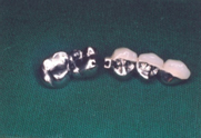
• Metal try-in of the individual units was done to verify proper seating [Table/Fig-6] .Then ceramic facing was added to right maxillary canine, first premolar, and second premolar.
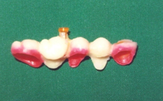
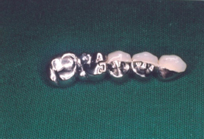
• Anterior segment with female portion and posterior segment with male portion were assembled together [Table/Fig-7,8] .
• During cementation, anterior three unit segment with keyway was cemented first followed by cementation of posterior two unit segment with key using glass ionomer cement [Table/Fig-9] .
The patient was instructed to maintain proper oral hygiene. Use of dental floss and interdental brush was recommended. The patient was evaluated after one week to assess the oral hygiene status [Table/Fig-10] .
Discussion
Connectors are the part of a fixed partial denture (FPD) that unites the retainers and pontics [1].Connectors may be rigid (solder joints or cast connector) or non-rigid (precision attachment or stress breaker). Rigid connectors between retainers and pontics are the preferred way of fabricating most FPD. They are not indicated in all situations like an edentulous space on either side of pier abutment [2].The selection of right type of connector during treatment planning is an essential step for success and failure of the prosthesis [3].
Teeth in different segments of the arch move in different directions. The facio-lingual movement of an anterior tooth occurs at a considerable angle to the facio-lingual movement of a molar, because of the curvature of the arch. These movements of measurable magnitude in divergent directions can create stresses in a long span prosthesis that will transferred to retainers and their respective abutments teeth [2]. Those forces are transmitted to the terminal retainers as a result of the middle abutment acting as a fulcrum, causing failure of weaker retainer [4]. Because of these dislodging forces rigid type of FPD with pier abutment have higher debonding rate than short span prosthesis, resulting in marginal leakage and caries [5].
Some way must be use to neutralise the outcome of those forces. The use of a non-rigid connector has been recommended to reduce this hazard. The non-rigid connector act as stress breaker between retainer and pontic instead of usual rigid connector. The movement in a non-rigid connector is enough to prevent the transfer of stress from segment being loaded to the rest of the FPD. The most commonly used non rigid connector consists of a T-shaped key that is attached to the pontic and a dovetail key way placed within the retainer [2].
Indication for non- rigid connector [6]:
• The existence of pier abutment which promotes a fulcrum-like situation that can cause the weakest of the terminal abutments to fail and may cause the intrusion of a pier abutment.
• The existence of the malaligned abutment, where parallel preparation might result in devitalisation. Such situation can be solved by the use of intracoronal attachment as connectors.
• Long span, FPD which can be distort due to shrinkage and pull of porcelain on thin sections of framework and thus, affect the fitting of the prosthesis on the teeth.
• In the mandibular arch, FPD consisting of anterior and posterior segments, a non rigid connector is indicated as the mandible flexes mediolaterally during opening and closing strokes.
• Disparity in retentive capacity of the abutments.
Contraindication for non- rigid connector[2]
• If the abutment presents significant mobility
• If the span between the abutments is longer than one tooth, because the stresses transferred to the abutment tooth under soldered retainer would be destructive
• If the posterior retainer and pontic are opposed by a removable partial denture or an edentulous ridge while the two anterior retainers are opposed by natural dentition.
This clinical case report discuss the use of non rigid connector between distal of second premolar retainer and mesial of first molar pontic where second premolar act as a pier abutment and canine and second molar act as terminal abutments.
The success of FPD depends on size, shape and type of connector [7] Factors such as overload, leverage, torque and flexing induce abnormal stress concentration in FPD. These abnormal stresses around connector and in the cervical dentine area near the edentulous ridge may leads to failure of long span FPD [8]. Photo-elastic stress analysis indicated that the prosthesis bends rather than rocks. This will create tension between terminal retainer and respective abutment. Intrusion of the abutments under the loading could lead to failure between retainer and respective abutments [9]. Savion et al., stated that the possible reason for debonding is development of extrusive reactive forces at the canine retainer as the first molar is loaded due to flexural forces developed within the FPD [10].
Advantages of non rigid connectors are they, transmit shear stresses to supporting bone rather than concentring them in connectors. It minimizes mesiodistal torquing of abutments and allow them to move independently [8]. Disadvantage of non rigid connectors are: (1) More tooth reduction of pier abutment, (2) Increased laboratory time and expense. (3) In the absence of occlusal stability some, key have been observed to lift off from their keyway [2].
There is conflict in opinion on placement site of non rigid connectors. Shillinburg et al, suggested the location of the non-rigid connector in the five unit pier abutment restoration placed on the middle abutment because placement on either of the terminal abutments could result in the pontic acting as a lever arm. The keyway of the connector should be placed within the normal distal contours of the pier abutment, and the key should be placed on the mesial side of the distal pontic. The long axes of the posterior teeth usually lean slightly in a mesial direction, and vertically applied occlusal forces produce further movement in this direction. If the keyway of the connector is placed on the distal side of the pier abutment, mesial movements seats the key into the keyway more solidly. [2]. This position has been supported by a finite element study conducted by Seluck Oruc et al., and observed that the area of maximum stress concentration occurs in pier abutments and it was decreased by the use of non-rigid connectors at the distal region of the second premolar [11]. However, Markley suggested that non-rigid connector should be placed at one of the terminal retainer, and emphasized that it should not be placed at the pier abutment because this would subject the relatively weak premolar abutment to extreme loads [12]. Gill recommended placing non rigid connector at one side or both sides of the pier abutment [13]. Admas advised placing one non rigid connector at the distal side of pier, and if desired adding one more at the distal of the anterior retainer[14].
Carl E Misch recommended that in conventional FPD, the ‘male’ portion of a non rigid connector usually located on mesial aspect of the posterior pontic; whereas, the ‘female’ portion is in the distal aspect of the natural pier abutment. This prevents mesial drift from unseating the attachment. However an implant does not undergo mesial drifting and the non rigid connector location is more flexible. For a natural pier abutment two implants, a stress breaker is not indicated [15].
The four types of non- rigid connectors are the [16]:
• Dovetail key-keyway or Tenon-Mortise type connectors.
• Cross-pin and wing type connector.
• Split type connector.
• Loop type connector.
The most common design of all used is Mortise female component placed within the contours of the retainers and a Tenon male component attached to the pontic. Accurate position of the dovetail shaped Mortise is critical; it must be parallel the path of withdrawal of a distal retainer [17].
Intraoral preoperative view
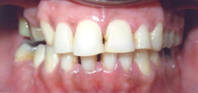
Missing right maxillary first premolar and first molar
Tooth preparation with right maxillary canine,second premolar and second molar
Wax pattern with male and female pattern
Anterior segment with key way mortise and posterior segment with key tenon
Anterior and Posterior segment joined together
Final prosthesis after cementation
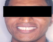
Post-operative extraoral view
Conclusion
The size, shape and type of connectors play important role in future success of a FPD. The selection of proper connector is important step in treatment planning of pier abutment. Non-rigid connectors transfer less stress to abutments also allowing physiologic tooth movement. Thus, the design and passive fit of non-rigid connectors is significant to success of a long span fixed partial denture.
[1]. Glossary of the Prosthodontics terms.J Posthet Dent. 2005 948th Edition:11-95. [Google Scholar]
[2]. JR Shillinburg HT, DA Sather, EL Wilson, JR Cain, DL Mitchell, LJ Blanco, Fundamental of fixed Prosthodontics. Chicago: Quintessence 2012 4:91-2. [Google Scholar]
[3]. S Banerjee, A Khongshei, T Gupta, A Baneerjee, Non-rigid connector: the wand to ally the stresses on abutment.Contemp Clin Dent. 2011 2:351-54. [Google Scholar]
[4]. JR Shillinburg HT, DW Fisher, Nonrigid Connectors for fixed partial denture .J Am Dent Assoc. 1973 87:1195-99. [Google Scholar]
[5]. MG Bothello, JE Dyson, Long-span fixed movable, resin bonded fixed partial dentures: a retrospective, preliminary clinical investigation.Int J Prosthodont. 2005 18:371-76. [Google Scholar]
[6]. PV Badwaik, AJ Pakahan, Non rigid connectors in fixed Prosthodontics: current concepts with a case report.J Ind Prostho Soc. 2005 5:99-102. [Google Scholar]
[7]. Tylman’s theory of fixed ProsthodonticsSt. Louis 1989 8:74-5. [Google Scholar]
[8]. JK Sutherland, GA Holland, TB Siuder, JT White, A photo elastic analysis of the stress distribution in bone supporting fixed partial denture of rigid and non rigid design.J Prosthet Dent. 1980 44:616-23. [Google Scholar]
[9]. JP Standlee, AA Caputo, Load transfer by fixed partial dentures with threeabutments.Quintessence Int. 1988 19:403-10. [Google Scholar]
[10]. I Savion, C Saucier, S Rues, A Sadan, M Blatz, The pier abutment: Review of literure and a suggested mathematical model.Quintessence Int. 2006 37:345-52. [Google Scholar]
[11]. S Oruc, O Eraslan, HA Tukay, A Atay, Stress analysis of effects of non rigid connector on fixed partial denture dentures with pier abutments.J Prosthet Dent. 2008 99:185-92. [Google Scholar]
[12]. MR Markley, Broken stress principle and design in fixed bridge prosthesis.J Prosthet Dent. 1951 1:416-23. [Google Scholar]
[13]. JR Gill, Treatment planning for mouth rehabilitation.J Prosthet Dent. 1952 2:230-45. [Google Scholar]
[14]. JD Adams, Planning posterior bridges.J Am Dent Assoc. 1956 53:647-54. [Google Scholar]
[15]. Contemporary Implant Dentistry. Elsevier Mosby,Carl E Misch. 2005 33rd Edition:263-64. [Google Scholar]
[16]. S Chaturvedi, AK Verma, P Vadhvani, Non –rigid connector: relay the stress.Ind J Dent Sci. 2012 4:53-5. [Google Scholar]
[17]. Pooja Parikh, Khyati Shah, Pathik Patel, Rajesh Sethuraman, YG Naveen, Tamanna Chhabra, Perceive means to manage pier abutments.European Journal of Dental Therapy and Research. 2013 3:160-66. [Google Scholar]