Introduction
In recent years, dental implant rehabilitation has faced demands from prosthetic and aesthetic arenas that call for increasingly ideal outcomes, which require a precise surgical planning and placement. Anatomic limitations and bone quantity and quality can now be evaluated by using more sophisticated radiographic techniques, although transferring this information to the surgical phase has been at best a difficult task [1]. Recently, computer-aided design and manufacturing [2–4] have made it possible to use data from computerised tomography to not only plan an implant rehabilitation, but also to transfer this information to the surgery. One of these techniques uses stereolithography, a laser-driven polymerisation process that fabricates an anatomic model and surgical templates [5–7]. This novel approach not only allows the precise translation of the treatment plan directly to the surgical field, but it also offers many significant benefits over traditional procedures.
The production of reformatted cross-sectional and panoramic image data which is presented as life-sized on an X-ray film or as a booklet of photographic-quality prints, has long been practised. A new alternative is now available: a surgery which is planned on the computer can be translated to the operation itself. That is, the 3D data which is obtained can be fed into a computer to assist with fulfilling the following primary objectives of implant planning:
(1) determination of available bone quantity and quality, (2) identification of nearby critical anatomic structures, (3) detection of pathology, (4) selection of actual implants from soft-ware-based libraries and catalogs, and (5) simulation of the surgical placement of implants which have been superimposed on 3D images, at their planned host sites [8].
Advantages of CAD/CAM Technology [
5–
7,
9]
Correct management of the tissues with minimal trauma and minimization of the need for decision making at the time of implantation.
3D technology allows a precise evaluation of anatomic points such as the size of the maxillary sinus in the upper jaw and location of the alveolar nerve in the lower jaw.
Precise analysis of Osseous Topography.
Provides information about size, direction, and bone location for accurate positioning of implants.
When it is fabricated on diagnostic study casts, the soft tissue is a rigid, non-functional representation and it does not provide information on the varying thickness of the mucosa, topography of underlying bone, or vital anatomical structures that lie within. In addition, the limitations of conventional dental radiography with regards to dimensional accuracy and inability in visualizing anatomical structures in parasagittal sections further hinders accurate evaluation.
Disadvantages of CAD/CAM Technology [
7]
Lack of visibility and tactile control during surgical procedure.
Insufficient mouth opening jeopardizes surgical procedure.
A risk of damage to vital anatomical structures.
Procedure
CAD/CAM technology in dental implant planning can be divided into following steps [
2,
6]
Fabrication of a radiographic template.
The computerised tomography scan procedure.
Implant planning by using interactive implant surgical planning software.
Fabrication of stereolithographic templates.
Surgical procedure.
Fabrication of a Radiological Template
A radiographic template allows the clinician to visualize the location of planned implants from a restorative standpoint [5]. It is a exact replica of the desired prosthetic end result. Various radioopaque markers such as gutta-percha balls and strips, metal pins and tubes, radioopaque varnishes and lead foil or barium sulphate in resin powder, aid in determination of the implant location [2,6]. By creating a diagnostic wax up or by duplicating an existing denture, the radiographic template can be fabricated [6]. While fabricating it, patient’s appropriate centric position and vertical dimension are noted. A vinylpolysiloxane interocclusal index is fabricated, which can be later used to stabilize the surgical template [2].
The Computerised Tomography Scan Procedure
Computerised Tomography (CT) is considered to be more accurate than conventional tomography, since it exhibits a uniform magnification. CT was founded by Sir Godfrey Houndsfield and Allen M.Cormack in 1972 [2,10]. The technique of dental CT, which is also called Dentascan, was developed by Schwarz et al., in 1987, when these investigators first used curved multiplanar reconstructions of the jaw [11]. When computed tomography, or more specifically, cone beam computed tomography or CBCT (3D X-ray imaging) is used pre–operatively to accurately pinpoint vital structures which include the inferior alveolar canal, the mental foramen, and the maxillary sinus, the chances of complications may be reduced, as are chair time and number of visits. Cone beam CT scanning, as compared to traditional medical CT scanning, utilizes less than 2% of the radiation, provides more accuracy in the area of interest, and is safer for the patient. CBCT allows the surgeon to create a surgical guide, which allows the surgeon to accurately angle the implant into the ideal space [10].
Helical CT, along with advancements in stereolithography, has allowed the development of a CAD/CAM processed surgical guide which can be placed on the bony site.But recently, cone beam CT has been recommended for dental imaging, as it presents identification of anatomical landmarks and provides high accuracy and low-radiation exposure levels [2,6,12].
Double Scanning Procedure
van Steenberghe D et al., introduced use of double scan procedure for integration of the radiological template within the craniofacial model [2,13]. A double-scan technique is used to acquire the CT data. Either spiral CT scanners or cone-beam CT scanners can be used. The data acquisition from the CT scan must be compatible and adequately detailed—slices of about 0.4 mm—to acquire images of the jaws which are being treated. The first scan is performed with the patient wearing the scanning denture and with the bite index in place, ensuring the correct placement of the denture and arrangement of teeth during the scan. The second scan is then performed with the scanning denture alone being positioned in the CT scanner, in the same orientation as it was in during the first scan. After the CT scanning procedures, the bite index is preserved for the upcoming laboratory procedure [14].
Implant Planning Stage
The computer software uses the radiopaque markers which have been laced in the scanning denture, to perform an accurate fusion of the two separate scans. Resulting from this fusion is an exact representation of the patient’s bone structure and scanning denture in 3D space. At this point, the virtual surgical procedure can be performed. In 1986, Fellingham et al.,[2, 8] first demonstrated the use of interactive graphics and 3D modelling for surgical planning, prosthesis, and implant design. By using the software, the dental team can select implants of specific lengths and diameters from a database of most commercially available implants and it can reproduce a 3D replica of exact dimensions in the desired location on the computer model of the patient’s jaw. Examples of such software programs are [2,6]:
SurgiGuides, Materialise, Leuven, Belgium
SIM/Plant, Columbia Scientific Incorporated, Columbia, MD
Nobel Guide, Nobel Biocave, Yorba Linda, CA
I-Dent Imaging Ltd., HodHasharon, IsraelcoDiagnostiX, IVS Solutions AG, Chemnitz, Germany
ImPlacer, Pacific Coast Software Inc., CA
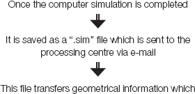
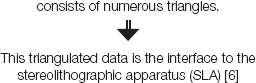
This 3D planning software allows an undistorted visualisation of the jawbone in four views: axial, cross-sectional, panoramic and 3D reformatted data. It allows 3D visualisation of all the anatomical structures which are situated within the bone and the prosthesis. Following is a flow chart which shows procedure which is followed once the data is obtained:
Fabrication of Stereolithographic Templates
In 1986, Dev et al.,[2,8] developed a computer-controlled, indirect milling machine for reproduction of an anatomical structure. Further development resulted in a rapid prototyping of stereolithography. A rapid prototyping machine which uses the principle of stereolithography is employed to fabricate the stereolithographic models. The SLA consists of a vat which contains a liquid photo polymerised resin. A laser which is mounted on top of the vat moves in sequential cross sectional increments of 1 mm, which correspond to the slice intervals which are specified during the CT formatting procedure. The laser polymerizes the surface layer of the resin on contact. Once the first slice is completed, a mechanical table which is immediately below the surface, moves down 1 mm, carrying with it the previously polymerised resin layer of the model [5–7,15].
The laser now polymerizes the next layer which is above the previously polymerised layer. In this manner, a complete stereolithographic model of the patient’s jaw can be created.
Approximately 80% of the total polymerisation is completed in the vat; the remaining 20% can be completed in a conventional ultra–violet light curing unit. The surgical templates are fabricated in a similar manner. They are built onto the surface anatomy of the stereolithographic model and are connected to it by a series of minute triangles that are later removed during the finishing process [6,13,15–16].
The SL machine also reads the diameter and angulation of the simulated implants and it selectively polymerizes resin which is around them, forming a cylindrical guide which corresponds to each implant. A technician removes supporting resin triangles and connects surgical grade stainless steel tubes into the cylindrical guide. In this manner, surgical templates which seat directly on the bone and have metal sleeves which correspond to each fixture site, are generated .Two sets of surgical templates which contain different sleeve diameters which correspond to the incremental size of the osteotomy drill which is being used, are required. The precise depth, angulation, and mesiodistal and bucco-lingual positioning of each implant, as are planned during the computer simulation, are pre-programmed in the template [2,6,15]. Windows on the buccal aspect allow access for external irrigation. Use in surgical procedures. The templates can be sterilised by using most common techniques without a loss of properties. These include low temperature steam and formaldehyde at 80ºC. The template itself has been fabricated from stereocol resin (Zeneca Specialties, Blackley, Manchester, UK), which is a photo-polymerised resin and it has been FDA-approved to accurately guide the osteotomy drills [6,16–17].
Surgical Procedure
At the time of surgery, stereolithographic template is seated directly on the bone. The unique surface topography of the bone, which is recorded by the CT scan and is incorporated in the S-L template, results in a precise fit without the need for an external fixation. Once the template is seated, the osteotomies are carried out. The configuration of the sleeves, as they relate to the drill, is such that there is only one direction for axial movement. Once the implants are placed, conventional protocol is followed, based on the implant system which is being used [2,6,15–17].
Discussion
Two of the most notable trends in modern surgical specialties are minimal invasive surgery and the integration of computerised diagnostics and computer-guided surgery. In oral implantology, these two trends are now main stream in the form on one side of the so called flapless surgery and on the other side of the computer-aided implantology. Even though flapless surgeries can be performed in some cases without the aid of a computer and though a computer-aided approach does not always allow a flapless procedure, these two approaches can often be combined with great advantage. They can be transformed in a relatively simple procedure, thanks to the Computer-Aided-Implantology (CAI) [4].
When an implant placement is planned in clinically challenging cases, several surveying techniques are available, among which Computerised Tomography (CT) has been shown to be among the most precise ones [17]. The two-dimensional representation which is rendered by the printed sections, however, is a limiting factor in interpretation and surgical planning of implant treatment [13].To address this concern, computer software packages have been designed to enhance clinical implant treatment planning through reading and interpreting CT scans, performing measurements, and evaluating anatomic relationships by placing virtual images on the screen (computer aided design [CAD]). Placement of a radiographic template prior to CT scanning further enhances treatment through visualisation of the proposed prosthetic plan with respect to underlying anatomic limitations [18].
Several software systems have been developed and they are being used on a large scale worldwide. Today, there are three practical methods for applying this technique in a clinical setting: guided surgery by using drill guides which are processed by stereolithographic rapid prototyping [15–17], computer-milled templates [19–21], and/or computer navigation systems [22]. Computer-milled templates are fabricated by drilling the final position of the implants in the scanning template itself, by using a drilling machine. Computer navigation systems allow an intraoperative real-time bur tracking according to the preoperative planned trajectory. Rapid prototypying is a method of producing solid, physical, hard copies of human anatomy from three-dimensional 3D computer data. Because CT is used to obtain 3D data from hard tissue structures, it is the radiographic modality that has the most applicability in computer guided implant diagnostics. These include: stereolithography, fused deposition modeling, and selective laser sintering. Each of these methods involve similar processings, which include data acquisition, image processing, and model production and finshing. Stereolithography is the most well known and used rapid-prototype technique. It is the technique which is commonly being used for the generation of computer-generated drilling guides which are used for osteotomy site preparations in dental implant surgery [2,3,6].
In this article, the technical steps which are involved in the generation of a stereolithographic template have been outlined, which have highlighted the significant advantages and disadvantages of CAD/CAM templates over traditional therapeutic methods in advanced implant rehabilitation.
Conclusion and Summary
Identification of the bony anatomy with respect to the teeth, prior to surgery, allows the clinician to place implants in areas where the implant–bone interface can be maximised and the prosthetic result is optimized. This is a tremendous advantage for both the clinician and the patient. The clinician can provide a treatment plan that reduces the operating time, surgical trauma, and postoperative recovery period which result from conventional freehand implant surgery, but which maintains a precise, stable, and a biomechanically sound outcome. The time which is saved with this revolutionary procedure is remarkable. There is no second-stage abutment connection surgery, no need for impressions, and no need for any additional clinical or laboratory procedures. The time which is required is minimum—a single 1-hour procedure versus numerous longer visits on following the traditional implant protocols. This is a significant advancement in implant dentistry and prosthodontics and it forces in making an interdisciplinary approach to the treatment of patients.
[1]. D’haese J, van de Velde T, Komiyama AI, Hultin M, Bruyn H, Accuracy and Complications Using Computer-Designed Stereolithographic Surgical Guides for Oral Rehabilitation by Means of Dental Implants: A Review of the LiteratureClin Implant Dent Relat Res 2010 14:321-35. [Google Scholar]
[2]. D’souza KM, Aras MA, Applications of computer-aided design/computer-assisted manufacturing technology in dental implant planningJ Dent Implant 2012 2:37-41. [Google Scholar]
[3]. Sohmura T, Kusumoto N, Otani T, Yamada S, Wakabayashi K, Yatani H, CAD/CAM fabrication and clinical application of surgical template and bone model in oral implant surgeryClin Oral Implants Res 2009 20:87-93. [Google Scholar]
[4]. Valente Sbrenna AF, Buoni BA, C C, CAD CAM Drilling Guides for Transferring CT-based Digital Planning to Flapless Placement of Oral Implants in Complex CasesInternational Journal of Computer Assisted Radiology and Surgery 2006 1:413-14. [Google Scholar]
[5]. Rosenfeld AL, Mandelaris GA, Tardieu PB, Prostheticallydirected implant placement using computer software toensure precise placement and predictable prosthetic out-comes.Part 2: rapid-prototype medical modeling and stereolithographic drilling guides requiring bone exposureInt J Periodontics Restorative Dent 2006 26:347-53. [Google Scholar]
[6]. Lal K, White GS, Morea DN, Wright RF, Use of stereolithographic templates for surgical and prosthodonticimplant planning and placement. Part I. The conceptJ Prosthodont 2006 15:51-58. [Google Scholar]
[7]. Sarment DP, Al-Shammari K, Kazor CE, Stereolithographic surgical templates for placement of dental implants in complex casesInt J Periodontics Restorative Dent 2003 23:287-95. [Google Scholar]
[8]. Voitik AJ, CT data and its CAD and CAM utility in implant planning: part IJ Oral Implantol 2002 28:302-3. [Google Scholar]
[9]. Jabero M, Sarment DP, Advanced Surgical Guidance Technology: A ReviewImplant Dentistry 2006 15:135-42. [Google Scholar]
[10]. Rothman SLG, Technique for computerised tomography of the jaws. In.:Dental Applications of Computerized Tomography – Surgical planning for implant placement 1998 LondonQuintessence Publishing Co, Inc:9-38. [Google Scholar]
[11]. Gahleitner A, Watzek G, Imhof H, Dental CT: imaging technique, anatomy, and pathologic conditions of the jawsEur Radiol 2003 13:366-376. [Google Scholar]
[12]. Widmann G, Bale RJ, Accuracy in computer-aided implant surgery - A reviewInt J Oral Maxillofac Implants 2006 21:305-13. [Google Scholar]
[13]. Vercruyssen M, Jacobs R, Van Assche N, van Steenberghe D, The use of CT scan based planning for oral rehabilitation by means of implants and its transfer to the surgical field: a critical review on accuracyJ Oral Rehabil 2008 35:454-74. [Google Scholar]
[14]. Balshi SF, Wolfinger GJ, Balshi TJ, Surgical planning and prosthesis construction using computed tomography, CAD/CAM technology, and the internet for immediate loading of dental implantsJ Esthet Restor Dent 2006 18:312-25. [Google Scholar]
[15]. Giovanni A.P Di Giacomo, Clinical Application of Stereolithographic Surgical Guides for Implant Placement: Preliminary ResultsJournal of Periodontology 2005 76:503-07. [Google Scholar]
[16]. Sarment DP, Sukovic P, Clinthorne N, Accuracy of implant placement with a stereolithographic surgical guideInt J Oral Maxillofac Implants 2003 18:571-77. [Google Scholar]
[17]. Ozan O, Turkyilmaz I, Ersoy AE, McGlumphy EA, Rosenstiel SF, Clinical accuracy of 3 different types of computed tomography-derived stereolithographic surgical guides inimplant placementJ Oral Maxillofac Surg 2009 67:394-401. [Google Scholar]
[18]. Ganz SD, Presurgical planning with CT-derived fabrication of surgical guidesJ Oral Maxillofac Surg 2005 63:59-71. [Google Scholar]
[19]. Fortin T, Champleboux G, Lormee J, Coudert JL, Precisedental implant placement in bone using surgical guidesinconjunction with medical imaging techniquesJ Oral Implantol 2000 26:300-03. [Google Scholar]
[20]. Fortin T, Champleboux G, Bianchi S, Buatois H, Coudert JL, Precision of transfer of preoperative planning for oralimplants based on cone-beam CT-scan images through arobotic drilling machineClin Oral Implants Res 2002 13:651-56. [Google Scholar]
[21]. Klein M, Abrams M, Computer-guided surgery utilizing acomputer-milled surgical templatePract Proced Aesthet Dent 2001 13:165-69. [Google Scholar]
[22]. Widmann G, Widmann R, Widmann E, Jaschke W, Bale R, Use of a surgical navigation system for CT-guided template productionInt J Oral Maxillofac Implants 2007 22:72-78. [Google Scholar]