The longevity and ultimate success of a cast restoration is often attributed to the accuracy of fit. This accuracy of marginal fit or adaptation may depend on various factors both clinical and laboratory. Certain clinical factors which have a major influencing role are the geometry of tooth preparation, such as design of finish line and total occlusal convergence, the impression technique, material used and finally the luting agent and the cementation technique used to cement the restoration [1,2]. The casting or the manufacturing technique employed and the proficiency in manipulation and use of various materials such as casting wax, die materials and investment materials also influence the final outcome with regards to the marginal and internal fit [3,4]. The accuracy with which patterns are fabricated also tends to affect the marginal adaptation of the final prosthesis. Taggart in 1907 introduced lost wax casting technique for casting alloys. Till date this technique sensitive method is used to make cast copings in fixed partial denture. Inaccurate marginal fit leads to dissolution of cement, plaque accumulation, increased chances of caries and periodontal diseases [5]. The success of any restoration mainly depends on three main factors: aesthetic value, resistance to fracture and marginal adaptation [6].
Computer-Aided Design/Computer Aided Manufacturing (CAD/CAM) technology was introduced to the dental community in the early 1980’s. Computer aided manufacturing is divided into two methods: 1) the subtractive method; and 2) the additive method.
One of the new techniques for fabrication of alloy copings by additive method reported in the literature is Direct Metal Laser Sintering (DMLS). DMLS is a 3 dimensional printing technique that can substitute the routinely used metal casting procedures [7]. The preferability of using CAD/CAM technology has gained significant momentum in fixed Prosthodontics. This is not just because of the obvious benefits such as minimisation of human error, reduction of manufacturing time and standardised fabrication protocol, but also because of its ability to design dental restorations with great accuracy and precision. CAD/CAM produces reproducible results and also decreases risk of human error [8]. A variety of different materials can be used with these newly developed CAD/CAM based additive and substractive techniques. Historically, precious alloys have been used more frequently for casting, but the popularity of base metal alloys has increased since 1970’s. Ceramics are nowadays widely used in dentistry due to their strength and aesthetics [9].
The development in new ceramic materials such as pressable glass based ceramics, zirconium oxide cores, CAD/CAM ceramics along with the use of different techniques like hot press, DMLS and CAD/CAM have paved a new way for restorations [10]. The fabrication of dental cast restorations with base metal alloys and other different materials by lost wax technique involves impression procedure, preparation of the die, fabrication of pattern, investing and casting. However, the casting procedure being largely manual in nature, difficulties and errors can be encountered at more than one junctures. This could potentially limit the use of these materials in dentistry. These difficulties can be minimised if new techniques are employed to replace the conventional casting procedures [8]. The marginal and internal fit of casted single crowns and fixed partial restorations have been the focus of many previous studies. These studies have used different parameters such as variations in types of preparation, impression methods, techniques of die preparation, materials and techniques used to fabricate patterns, conventional and accelerated casting protocols [11-13]. Fewer studies, however concentrated on evaluating the marginal accuracy of restorations using a variable combination of newer all-ceramic materials, conventional base metal alloys and recent techniques such as like CAD/CAM, HOT PRESS and DMLS [14-16].
Considering the relative paucity of such studies, the current invitro study was conducted to compare and evaluate the vertical marginal adaptation of CAD/CAM Zirconia, Pressable Lithium Disilicate, CAD/CAM Cobalt Chromium and DMLS Cobalt Chromium copings. The purpose of the study is to enable the clinician and technician to make an informed choice when it comes to selection of the most appropriate material in combination with an appropriate processing technique to achieve better clinical results.
The null hypothesis for the study was that there would be no difference in the vertical marginal adaptation of copings fabricated using these four techniques.
Materials and Methods
The current invitro study was undertaken at Bharati Vidyapeeth Dental College and Hospital, Pune from November 2018 to October 2019. No patient related data was used in this study and hence no ethical committee approval was required.
Master Die Fabrication
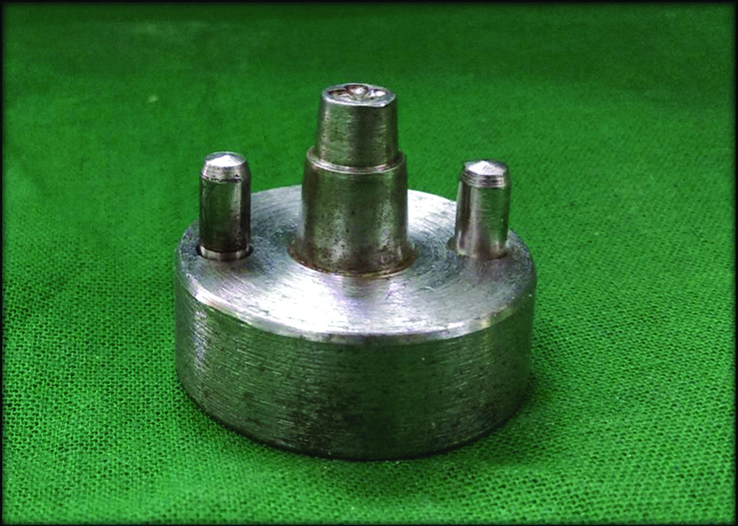
A custom-made metal master model [Table/Fig-1] was prepared simulating the shape and dimension of tooth preparation resembling the first premolar using a CNC Milling Machine (Datron D5, Datron, India) [2].
The copings were fabricated by a single operator who was an expert in the field of Prosthodontics and Crown and Bridge with the help of dental technicians who were experienced and adept in the techniques and systems used in the study. All measurements of precision of marginal fit were performed by a single technician without knowledge of the identity of the testing groups used in the study to avoid any inter-investigator variation as far as possible. Intraexaminer reproducibility results were consistent for all measurements, intra class correlation coefficient (0.80-0.96).
The stainless steel master model employed in this study was custom made, based on the model employed by Ushiwata O and Moraes JVde for their studies with a little modification [2]. The master die simulated a crown preparation with a 6° total axial wall taper. The axial height of the die and its occlusal diameter were 6 mm and the finish line was a 90° shoulder, 1 mm in width. Occlusal cross hairs were placed for precise wax pattern repositioning.
Stone Die Fabrication
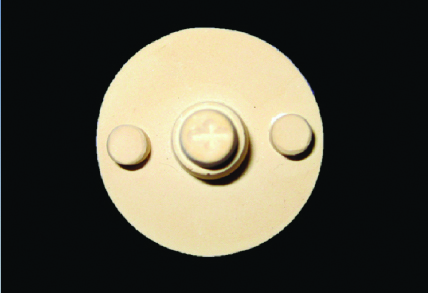
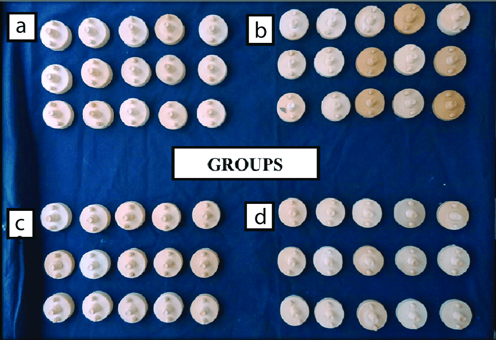
An elastomeric impression of the custom-made stainless steel model was made using addition silicone (3M ESPE, Germany) using dual mix/double step technique. This technique was employed for its accuracy and ease of use. Type IV dental stone (Ultra rock, Kalabhai) was mixed in w/p ratio (0.22) recommended by the manufacturer and was poured into the mould. After setting a single stone die was obtained which was used for fabrication of the coping [Table/Fig-2]. Similarly, 60 stone dies were obtained and these dies were divided into four groups- Group A (CAD/CAM Zirconia), Group B (Pressable Lithium Disilicate), Group C (CAD/CAM Cobalt Chromium) and Group D (Direct metal Laser Sintered Copings), respectively. Each group had 15 samples (stone dies) [Table/Fig-3]. The sample size (n=60) was estimated by fixing the significance level of the study at 0.05 and power of the study was set at 90%.
Duplicated die in die stone material.
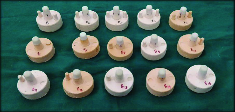
(a-d) 60 Stone dies divided into four groups.
Group A- CAD/CAM Zirconia, Group B- Pressable Lithium Disilicate, Group C- CAD/CAM Cobalt Chromium, Group D- Direct metal Laser Sintered Copings
Fabrication of CAD/CAM Zirconia Copings
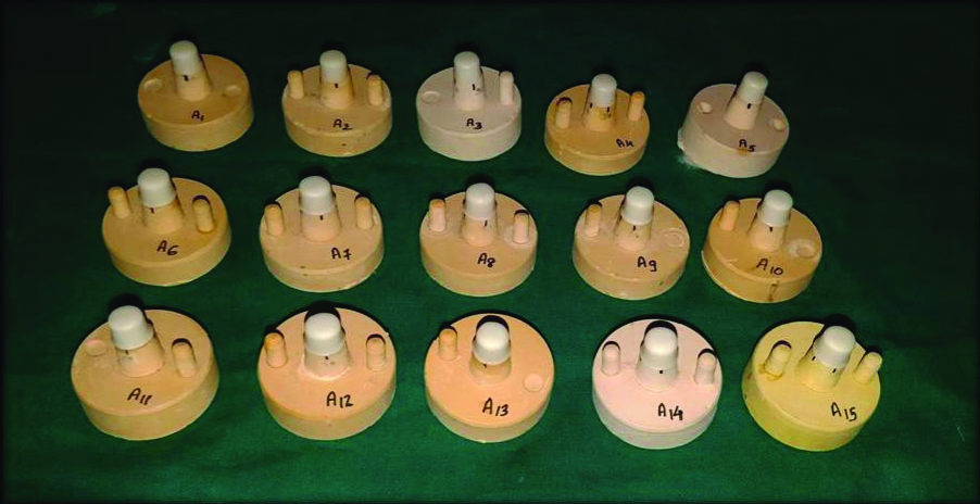
Ceramill Map300 CAD/CAM system (AmannGirrbach AG. Koblach, Austria) was used to fabricate the 15 zirconia copings used in this study. Stone model was scanned using a lab scanner (Amann Girrbachceramill map 300). Scanned data were then converted into CAD data. No cement space was included for the margin and 50 μm was set for the the axial and occlusal surfaces. Thickness of the copings was designed to be 0.5 mm. The position of the finish line (preparation limit) was marked on the die using the computer software and a coping was designed on the screen by the CAD module. Design data were converted into processing data using the Ceramill CAD software and sent to the processing machine (Ceramill Motion 2). The zirconia blocks (IVOCLAR ZENOTEC) were cut and milled, and then the milled blocks were finally sintered to make zirconia copings. The copings were evaluated for imperfections and faulty samples were discarded. The complete seating of the copings was evaluated under an illuminated magnifying lens (2x magnification). During cementation, each coping was seated on its respective stone die under a constant load of 2 kg (approximately 20 N) applied on the occlusal surface to ensure complete seating of the coping. After the entire procedure 15 copings were obtained which were labelled as group A test samples and numbered [Table/Fig-4].
Zirconia copings-Group A test samples.
Fabrication of Pressable Lithium Disilicate Copings
Fifteen copings were fabricated from lithium disilicate glass ceramics (IPS e-max press, IvoclarVivadent, AG) by the combination of CAD/CAM wax patterns and heat press techniques. Cement space of 50 μm was set for the axial and occlusal surfaces of the abutment. A cement space 50 μm was chosen to ensure better seating of coping by providing sufficient space for the Glass ionomer cement (GC Corporation Tokyo, Japan) and its uniform distribution along the axial surfaces. This necessary space also helped in minimising premature contacts on the internal or fitting surface of the coping [17,18].
Thickness of the copings was set to be 0.5 mm. The transformation to STL format was carried out and sent to CAM software for manufacturing of the wax patterns. The wax copings were invested in a phosphate bonded carbon-free investment (Bellavest SH; Bego). Once the investment had set, the wax was eliminated and the ceramic ingot (IPS e.max; IvoclarVivadent AG) was pressed in the Hot Press System (IVOCLAR VIVADENT 3000 PROGRAMMAT). The pressed copings were divested, separated and cleaned by applying 1% of hydrofluoric acid (IPS e.max Press Invex Liquid, IvoclarVivadent AG). The internal surface of the copings was evaluated for imperfections, nodules and irregularities under an illuminated magnifying glass (2x magnification). The nodules were removed with a round diamond bur along with water coolant. After completion of the procedure 15 copings were obtained which were labelled as group B test samples and numbered [Table/Fig-5].
Lithium disilicate copings-Group B test samples.
Fabrication of CAD/CAM Cobalt Chromium Copings
A total of 15 stone dies were scanned with a scanner (Ceramill Map300 CAD/CAM system). The models were then used to design the copings using a CAD software program (CeramillAmammGirrbach). The thickness was set to 0.5 mm and an internal space of 50 μm was provided on the axial and occlusal surface of the scanned model. The data pertaining to the completed design was saved as an STL file and fed into a milling machine (DATRON D5). Metal blanks (DENTFLOW) were then milled to fabricate the Cobalt-Chromium Alloy (Co-Cr) alloy copings. After completion of the procedure 15 copings were obtained which were labelled as group C test samples and numbered [Table/Fig-6].
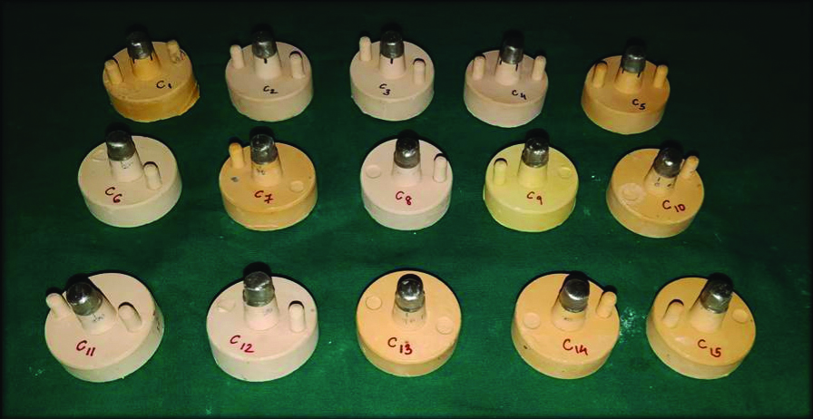
CAD/CAM cobalt chromium copings – Group C test samples.
Fabrication of Direct Metal Laser Sintered Copings
The virtual design of the DMLS copings was finalised using the same design technique as stated above with the CAD software program. Cement space of 50 μm was set for the axial and occlusal surfaces of the abutment. The fabrication of the copings was then done using a DMLS machine (EOSINT M270; EOS GmbH, Krailling, Germany) and Co-Cr powder (EOS Cobalt Chrome SP2) which was sintered using a laser beam. The powder was sintered to a layer thickness of 20 μm at a building speed of 2-20 mm3/s from the incisal edge to the margin at 1500°C in an inert gas environment (nitrogen atmosphere). After the first layer solidified the built platform moved another layer of powder, which was again sintered by the laser beam. The process was repeated until the coping was completed. After completion of these procedures 15 copings were obtained which were sandblasted with 110 μm aluminium oxide powder (Korox 110 Crndm Blast, Bego) and steam cleaned and labelled as group D test samples and numbered [Table/Fig-7].
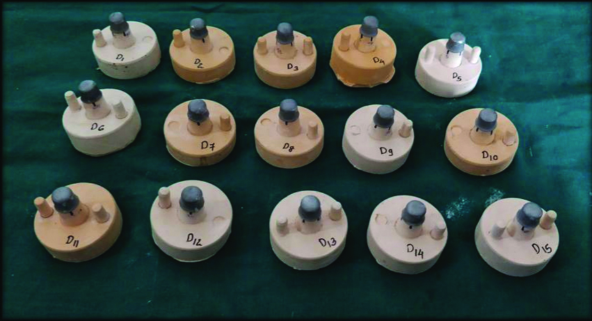
Direct metal laser sintered copings – Group D test samples.
Cementation of the Fabricated Copings on the Stone Die
All the 60 copings were cemented on the stone dies using Glass Ionomer Cement (GC Corporation Tokyo, Japan). The cement was proportioned and manipulated adhering to the manufacturer’s instructions and applied uniformly to the internal surface of the copings. Each coping was seated on its respective stone die under a constant load of 2 kg (approximately 20 N) applied on the occlusal surface for 10 seconds. Excess cement was removed with an explorer and afterwards was checked for the marginal fit accuracy through a digital optical stereomicroscope (Wuzhou New Found Instrument Co. Ltd, China, Model: XTL 3400E) at Praj metallurgical Laboratory, Pune. A magnification of 20x was used for the measurement of the vertical marginal discrepancy.
Measurement of Vertical Marginal Fit
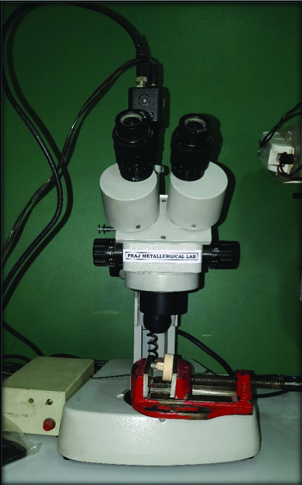
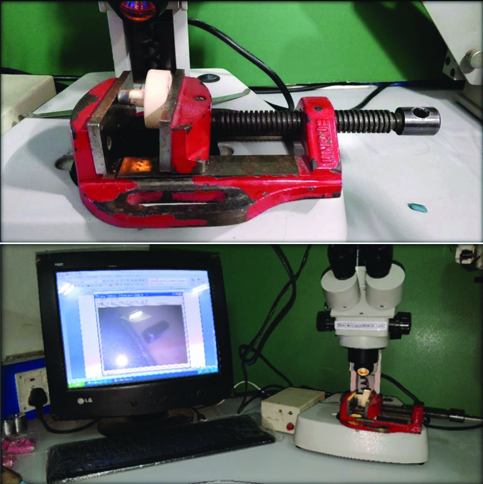
Measurements were made using a digital optical stereomicroscope (Wuzhou New Found Instrument Co. Ltd, China, Model: XTL 3400E) [Table/Fig-8], with an accuracy of 0.1 μm. Stereomicroscopic images of the stone die-coping assembly were recorded at a magnification of 20X to evaluate the vertical marginal discrepancy. Measurements for the vertical marginal gap (in microns- μm) were made between the margin of the casting and the reference marks scribed on the die stone at four points on the centre of each surface on the vestibular side of the finish line of the prepared tooth i.e., 0° (Buccal surface), 90° (Mesial Surface), 180° (Lingual surface) and 270° (Distal surface) on the stone die [Table/Fig-9]. A fine indelible mark was placed on the margin of coping corresponding to the reference marks on the stone die. A total of 240 measurements were made (4 readings for each sample). All measurements were performed by the same operator without knowledge of the identity of the testing groups.
Statistical Analysis
Descriptive and inferential statistical analysis were carried out in the present study. The statistical software SPSS 20.0 (IBM Corporation, Armonk, NY, USA) was used for the analysis of the data. Analysis of Variance (ANOVA) was used to find the significance of study parameters between the groups. Further Tukey’s post-hoc analysis was carried out if the values of the ANOVA test were significant. The level of significance was fixed at p=0.05 and any value less than or equal to 0.05 was considered to statistically significant.
Measurements for the vertical marginal gap were made at 4 points, one on each of the 4 surfaces of each sample i.e., 0° (Buccal surface), 90° (Mesial Surface), 180° (Lingual surface), and 270° (Distal surface).
Results
The results support the rejection of the null hypothesis as there was a significant difference in the vertical marginal fit between the 4 groups. The difference in the vertical marginal gap of the copings obtained from the groups was statistically significant. The copings obtained from DMLS technique showed statistically significant minimum value followed by CAD/CAM Zirconia copings followed by Pressable Lithium Disilicate copings. The copings obtained from CAD/CAM Cobalt Chromium showed maximum vertical marginal gap.
On overall comparison of vertical marginal fit accuracy of Group A, Group B, Group C and Group D copings under stereo microscope it was found that the mean marginal discrepancy of Group A was found to be 53.185±25.83 μm, marginal discrepancy of Group B was found to be 66.08±22.27 μm, marginal discrepancy of Group C was found to be 108.62±23.93 μm and marginal discrepancy for Group D was found to be 28.54±13.53 μm, respectively. On comparision of all the four groups using ANOVA F test, it was found that highly significant difference existed in relation to their mean marginal discrepancy (F=35.108, p<0.001**). Least marginal discrepancy was found for Group D followed by Group A followed by Group B and Group C, respectively [Table/Fig-10].
Stereomicroscope (Wuzhou New Found Instrument Co. Ltd., China, Model: Xtl 3400e).
Sample being measured under stereomicroscope.
Comparison of the marginal gap in terms of {Mean (SD)} among all the groups using ANOVA test.
| Group | N | Mean (μm) | Std. deviation (μm) | F value | p-value |
|---|
| Group A (CAD/CAM Zirconia) | 15 | 53.185 | 25.8360 | 35.108 | <0.001** |
| Group B (Pressable Lithium Disilicate) | 15 | 66.086 | 22.2761 |
| Group C (CAD/CAM Cobalt Chromium) | 15 | 108.623 | 23.9312 |
| Group D (Direct metal Laser Sintered Copings) | 15 | 28.545 | 13.5323 |
| Total | 60 | 64.110 | 36.2237 |
*(p<0.05-Significant*, p<0.001-Highly significant**)
Tukey’s post-hoc analysis was used to compare the marginal fit amongst different groups [Table/Fig-11]. The mean difference in Group D and other three groups was statistically significant (p<0.05) at 95% confidence so Group D exhibited the lowest marginal discrepancy among the four groups.
Comparison of the marginal gap in terms of {Mean (SD)} among all the groups using Tukey’s Post-hoc analysis.
| Group A | Group B | Group C | Group D |
|---|
| Group A (CAD/CAM zirconia) | - | 0.380 | <0.001** | 0.016* |
| Group B (Pressable lithium disilicate) | 0.380 | - | <0.001** | <0.001** |
| Group C (CAD/CAM cobalt chromium) | <0.001** | <0.001** | - | <0.001** |
| Group D (Direct metal laser sintered copings) | 0.016* | <0.001** | <0.001** | - |
The mean difference in Group C and the other three groups was statistically significant (p<0.05) i.e., marginal discrepancy of group C was more than Group A, Group B and Group D.
The mean difference in Group A and Group B was not statistically significant (p>0.05).
Hence the accuracy of vertical marginal fit among the groups was Group D > (Group A=Group B) > Group C.
Discussion
The present invitro study was conducted to comparatively evaluate the vertical marginal fit of CAD/CAM Zirconia, Pressable Lithium Disilicate, CAD/CAM Cobalt-Chromium and Direct Metal Laser Sintered Cobalt Chromium copings. The results of the study indicated that the technique and the protocol used for the fabrication had a definite influence on the marginal gap of an indirect restoration. The results support the rejection of the null hypothesis as there was a significant difference in the vertical marginal fit between the four groups. The difference in the vertical marginal gap of the copings obtained from the groups was statistically significant. The copings obtained from DMLS technique showed statistically significant minimum value followed by CAD/CAM Zirconia copings and Pressable Lithium Disilicate copings. The copings obtained from CAD/CAM Cobalt-Chromium showed the maximum vertical marginal gap.
The fabrication of acceptable copings is an important variable that can affect marginal and internal fit of the restoration. Many factors like preparation of tooth, manipulation or compatibility of dental materials used both in clinical and laboratory affect the overall acceptability of cast restorations [19]. Poorly fitting dental prostheses have been known to be associated with oral health diseases in patient’s particularly secondary or recurrent caries and periodontal inflammation [20]. Recently, introduced systems like computer aided design/computer aided manufacturing, three dimensional printing, DMLS are being rapidly used to fabricate indirect restorations. Also, all ceramic restorations are nowadays widely preferred in dentistry due to their aesthetic advantages and significant improvement in strength parameters [9].
Due to variations in size, shape and structure of the natural teeth in clinical practice there is a hindrance in obtaining abutments which are standardised for research purpose, which could affect the overall authenticity of the study results [21]. Therefore in present study, stone dies were fabricated from the standardised master die.
In order to reproduce the clinical condition, Lacy AM et al., suggested that any study aimed at determining the marginal adaptation of a crown system requires the cementation of the crowns [22]. In present study, the marginal discrepancy was measured after the cementation of the copings as it could potentially affect the marginal adaptation. Each coping was seated on its respective stone die under a constant load of 2 kg (20 N) applied on the occlusal surface for 10 seconds. Grooves on the occlusal surface of the die prevented rotation of the copings. Excess cement was removed with an explorer and afterwards was checked for marginal fit through a stereomicroscope.
The basic data obtained in this study shows a mean vertical marginal gap of 53.185 μm for CAD/CAM zirconia copings (Group A), 66.086 μm for Pressable Lithium Disilicate copings (Group B) 108.623 μm for CAD/CAM Cobalt Chromium copings (Group C) and 28.54 μm for Direct Metal Laser Sintered copings (Group D).
In the present study, the readings for the marginal accuracy of CAD/CAM Zirconia copings were found to be better than that of Pressable Lithium Disilicate copings. Riccitiello F et al., proved that CAD/CAM zirconia crowns showed greater precision fit at the marginal level than heat pressed Lithium disilicate crowns [14].
However in the current study, the difference between these two groups was not found to be statistically significant. A possible explanation could be that CAD/CAM milled wax patterns were used to fabricate the lithium disilicate copings which improved the marginal fit of the copings and reduced the difference in the marginal gap between the two groups [23]. It is also worthy to note, that certain studies comparing the marginal fit of pressed and CAD/CAM lithium disilicate crowns found the pressed crowns exhibiting better marginal fit [24,25]. This fairly suggests that pressable Lithium disilicate crowns have a reasonably accurate and clinically accurate fit.
Mean vertical marginal gap of the cobalt chromium copings obtained using DMLS technique (Group D) 28.54 μm was the least when compared to the remaining three groups. This could be a result of complete elimination of manual errors involved in the investing and casting procedures. This finding can be because of the fact that fabrication of direct metal laser sintered copings employs an additive manufacturing technique uses a high powered laser to sinter particles of the metal powder together, layer by layer to form a 3 dimensional object of the desired shape and size [9].
The mean vertical marginal discrepancy for CAD/CAM Cobalt Chromium copings 108.623 μm was found to be the highest. The findings of current study were consistent with the study by Örtorp A et al., who found that cobalt chromium fixed partial dentures (3-unit) fabricated using DMLS technique led to a narrower gap whereas those fabricated using computer-aided milling technique produced the widest gap of all [26]. A study by James AE et al., also came to a similar conclusion that CAD/CAM milled Co-Cr crowns exhibited a wider marginal gap as compared to DMLS crowns [27]. Also the copings of Group A and Group C were obtained by subtractive method. The subtractive method of computer aided manufacturing limits the accuracy of fit of the internal surface of restoration as it is influenced by the dimension of the smallest fitting tool that has been used for a particular material of a system. If the diametric dimension of the milling bur is larger than certain surfaces, line or point angles of the prepared tooth, it will have a negative influence on the precision of milling process and consequently result in decreased internal fit precision or inferior marginal properties [28].
CAD/CAM Cobalt Chromium copings in this study show more marginal gap when compared to all the other three groups. In a similar study, conducted by Dixit SY et al., [15] it was found that the CAD/CAM Zironia copings showed better marginal fit as compared to SMLS Co-Cr and Pressable Lithium Disilicate copings which is contradictory to the results of the present study. This could probably be because a different CAD/CAM system, 3M LAVA CAD/CAM system (3M ESPE Dental Products St. Paul, MN USA) was used to fabricate zirconia copings and the marginal adaptation could vary depending on the CAM system used [29]. Also, the copings were not cemented and the measurements for marginal gap were directly made on the prepared metal die. This also can be cited as one of the reasons for the variation in the results as compared to the present study.
Doddy L et al., in their study also concluded that CAD/CAM Zirconia showed lesser mean marginal gap as compared to DMLS Co-Cr [16]. However, a limitation of this study was the use of finger pressure for the cementation of the copings which could have led to incomplete seating of the copings and variable results as the pressure was not standardised. All specimens for fabrication of CAD/CAM Zirconia copings (Group A) and CAD/CAM Cobalt-Chromium (Group C) were scanned with the identical machine but with different processing routes. The metallic copings were fabricated from hard solid presintered Co-Cr blocks in a high-speed milling process (DATRON D5 5-Axis Dental Milling Machine) using tungsten-carbide instruments under constant water cooling while Zirconia copings were milled from soft presintered zirconia blanks (IVOCLAR Zenotec) in a dry state [30] using diamond burs. The differences in milling and the differences in the instruments used (tungsten-carbide versus diamonds) might be an influencing factor for the achievable marginal accuracy. Also, the Co-Cr alloy block of the milled group due to its hardness is more difficult to cut. Increased vibration and resistance of the milling axis during preparation affects the accuracy of the milling procedure. Kim MJ et al., performed a study in which copings fabricated by casting showed least vertical marginal gap values as compared to the copings fabricated using CAD/CAM milling and 3-D laser sintering [31].
The marginal discrepancy CAD/CAM Cobalt-Chromium copings were more than the Pressable Lithium Disilicate copings. The probable reason for this finding can be attributed to the CAD/CAM milled wax patterns and the accuracy of die spacer in the CAD/CAM software. Regardless of the technique used to fabricate wax patterns, some amount of distortion may occur, primarily on account of relaxation of internal strains developed in the wax. To avoid this, efforts should be concentrated towards investment of the pattern promptly as soon as it is removed from the working cast or the die [32]. In the present study, this rule was respected. The difference in the marginal fit could be the result of the difference in the wax distortion pattern between the manual and the milled wax. These differences are mainly related to the flow properties, shrinkage and expansion after the unequal heating and cooling of the manually fabricated wax, while the wax used for CAD/CAM is a solid synthetic wax produced from polymerization reaction and is less sensitive to temperature conditions [33]. So along with the efficiency of the Ceramill Software which was used to fabricate the wax patterns with increased precision without any chance for manual or technical error and the above mentioned reasons this might be the probable cause for better marginal accuracy of Pressable Lithium Disilicate copings than the CAD/CAM Cobalt-Chromium copings. Also, differences in the marginal fit could be explained by the accurate setting of the digital die spacer in the CAD/CAM technique while in the manual fabrication of wax pattern the die spacer is variable. This difference is accounted for by the evaporation of the liquid. This was in accordance of Shamseddine L et al., who in their study concluded that lithium disilicate crowns showed better marginal fit and internal adaptation when wax patterns milled by subtractive manufacturing were used as compared to wax patterns fabricated by conventional waxing technique [23]. Also, the Co-Cr alloy block, of the milled group, by virtue of its hardness is difficult to mill with precision hence influencing the accuracy of the milling procedure [29]. The accuracy of the marginal and internal fit of indirect restorations is inherently vital to their longevity and successful service in the oral cavity. McLean and von Fraunhofer suggested that a marginal gap of 120 μm falls within the clinically acceptable range and this has been generally acknowledged by many studies as a standard for maximum tolerable limit for marginal discrepancy [34]. The results of present study suggested that the mean vertical marginal gap for all four groups (60 samples/copings) was in the range of 28.54-108.62 μm. These readings were within the acceptable range and in consensus with those of McLean JW and von Fraunhofer JA [34]. Groten M et al., reported that approximately 50 measurements were needed for clinically relevant information about the gap size regardless of the gap definition or cementation condition [35]. The results would then be more confirmative in nature and therefore more clinically applicable.
Limitation(s)
In the present study, horizontal marginal fit/internal fit was not evaluated. The current study being an invitro study gives an insight into marginal accuracy of the various materials and techniques used in this study. However, the results cannot be directly applied into clinical situations. High cost of the tools, complicated machinery engaged and dependency on the expertise to run the machinery during production could also be one of the limitations of the study.
Conclusion(s)
The marginal fit of DMLS copings is more accurate as compared to CAD/CAM Zirconia, Pressable Lithium Disilicate and CAD/CAM Cobalt-Chromium copings. The DMLS technique displayed the least vertical marginal gap and therefore has an upper hand on the other techniques that were used in this study. Also, CAD/CAM Cobalt-Chromium copings exhibited a significantly higher discrepancy compared to the other three groups. The measurements made for the marginal fit of the copings in this study were within the range of clinically acceptability. With the advent of so many technological enhancements in the field of clinical dental practice and research, continued investigation and study of newer techniques and materials is definitely suggested both invivo and invitro in nature.
*(p<0.05-Significant*, p<0.001-Highly significant**)