Due to complex nature of Mandibular Angle Fractures (MAF), fixation surgery carries a significant risk of morbidity [1] and common post-operative complications include alveolar osteitis and pathologies of the periodontal region and temporomandibular joint [2,3]. In particular, close proximity of the third molar (M3) to the mandibular canal in which the Inferior Alveolar Nerve (IAN) runs, poses a high risk of iatrogenic injury, which can result in mental paraesthesia or anaesthesia. This is further complicated by variations in M3 morphology and its Three-Dimensional (3D) spatial relation to the canal. Incidence rates vary but a review by Tuzi A et al., reported a 0.2-0.9% risk of permanent and 3.3-13% risk of reversible IAN injuries respectively [4]. Good pre-operative imaging and surgical planning can reduce this and individualised risk profiles will allow better patient counselling.
Existing M3 imaging modalities include (standard intraoral, panoramic and extraoral) plain radiography, (standard, cone beam and tuned aperture) Computed Tomography (CT) and Magnetic Resonance Imaging (MRI) [5]. Current clinical practice involves panoramic radiography for routine cases and research and CT for complicated ones [6]. However, these are not without shortcomings. Panoramic radiography inaccurately describes M3 root morphology as it lies outside the center of rotation of the detector leading to distortion and magnification differences [7]. 3D interpretation is also impossible as buccolingual information is lacking [4]. Though CT offers better geometric accuracy and resolution of bony structures [8], it is still two-dimensional (2D).
To overcome this, 3D models can be constructed from 2D CT scan DICOM (Digital Imaging and Communications in Medicine) data to visualise previously hidden surfaces and allow greater interactivity through user-controlled rotation in any direction [9,10]. In addition, digital isolation of interfaces is possible, making it easier to delineate bone from soft tissue.
OsiriX version 7.5 (Pixmeo., Switzerland) is an open-source user friendly DICOM image processing software that can convert 2D CT scan images into a 3D model from volume acquisitions in a Virtual Operating Room (VOR) developed by Rosset A et al., at the University of Geneva for the Mac OS X operating system [11,12]. The software can also provide thick-slab Maximum Intensity Projections (MIP), orthogonal and oblique multiplanar reformatting (MPR), and 3D surface and volume rendering images. The 3D volume rendering and MPR images are most useful for pre-operative evaluation surgical planning and 3D coordinates can be plotted for anatomic and kinematic analyses [13].
As the DICOM server is included within the software, a Picture Archiving and Communication System (PACS) can be built, allowing navigation through large sets of multi-dimensional data on personal computers with minimal processing from its central processing unit. This obviates the need for expensive dedicated workstations, making it highly affordable and portable. With these potential advantages in mind, our study attempts to apply OsiriX to M3 evaluation in the context of MAF repair.
Materials and Methods
A retrospective analysis of the Computed Tomography (CT) scans and demographic data of 23 subjects with 25 MAFs (2 subjects had bilateral MAFs) from an existing local database was performed. These subjects were managed by surgeons from the Plastic, Reconstructive and Aesthetic Surgery department of a single centre (National University Hospital, NUH, Singapore) between January 2001 and December 2010.
Inclusion and Exclusion Criteria
Open reduction and internal fixation with M3 retention was performed in all cases and all subjects were discharged well. They were subsequently followed-up as outpatients at one and six months postoperatively. Those who were below 16 years of age and was managed conservatively were excluded. Subjects with complete follow-up and adequate CT scan imaging were analysed. Fine cut (1 mm slice interval) CT scans of the mandible, facial skeleton and head were used, as long as the mandibular angle was well visualised. If more than 1 scan was available, the one with the better resolution was selected. Subjects with bilateral MAF were logged as separate entries.
CT Measurements
OsiriX was used to measure the intraosseous M3 length (L) and diameter (D) and the mandibular height (H) and width (W). As a surrogate measure of osseous volume occupied by the M3 vertically and horizontally, the ratio of the mean intraosseous M3 length to mean mandibular height (L/H) and mean intraosseous M3 diameter to mean mandibular width (D/W) were calculated respectively.
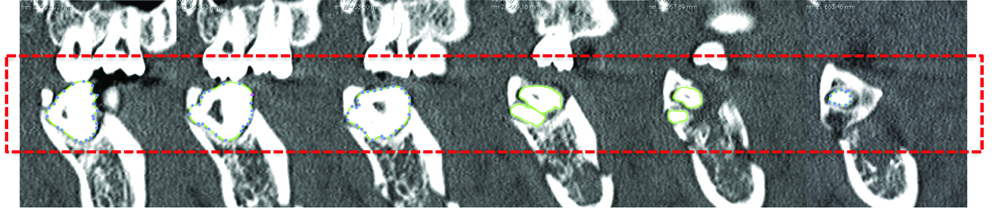
To isolate the M3, manual segmentation was done on each CT slice. Pixel density differences were used to identify boundaries and Region Of Interest (ROI) markers were placed along this edge. OsiriX then summated these ROIs into a 3D image of the M3. An example of this has been shown below in [Table/Fig-1a,b].
Example of manual segmentation of M3.
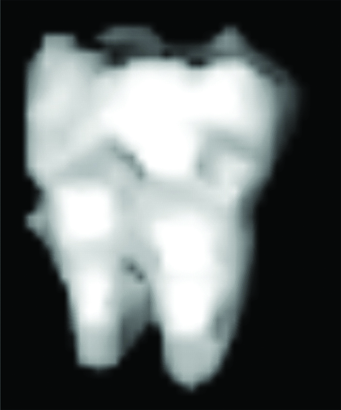
Resultant 3D model of M3.
To measure M3 variables, two points were placed on this model and their coordinates recorded. Lines were drawn between these points to ensure accurate placement of points. An example of image manipulation and point placement has been shown in [Table/Fig-2].
Example of image manipulation and point placement.

Intraosseous M3 Length and Mandibular Height
For intraosseous M3 length, the model was manipulated and one point each placed on the highest and lowest part of the M3 within the mandible. A line formed by these two points was approximately parallel to the ramus. For mandibular thickness, one point each was placed on the most superior and inferior point of the ramus. A line formed by these two points was approximately parallel to the ramus as well.
Intraosseous M3 Diameter and Mandibular Width
Similarly, for intraosseous M3 diameter, the model was manipulated and one point each placed on the medial and lateral aspect of the M3 within the mandible. A line formed between these two points was perpendicular to the ramus. For mandibular width, a point each was placed on the medial and lateral aspect of the mandible. A line formed by these two points was perpendicular to the ramus as well.
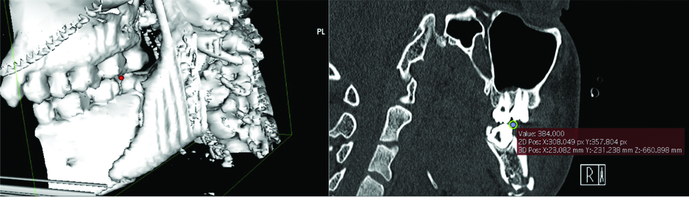
Accuracy checking was done by reconfirming point placement in the 2D-viewer. The coordinates in x, y, z format were input into Excel (Microsoft®, Washington) and distances automatically generated. An example of point placement and coordinate checking has been shown below in [Table/Fig-3].
Example of point placement and coordinates checking.
Reliability Indices
All measurements were done by one of the authors and repeated by a second author to asses for repeatability. Inter and intra-observer variability was assessed for using Cronbach’s Alpha (CA) and Interclass Coefficient Correlations (ICC).
Statistical Analysis
Statistical Package for Social Sciences (SPSS) version 23.0 (IBM Corp., Armonk, NY) was used for database construction and analysis. Parametric tests were performed and statistical significance set at p<0.05.
Results
A total of 23 subjects were included in this study (46 mandibular angles and M3s) and of these, 25 were MAFs (54.3%). The ratio of left:right mandibular angles was 11:14 and 10:11 in fractured and non-fractured sites respectively.
Measurements were performed thrice (twice by author AK and once by author CD) and averaged. The average mean (Standard Deviation, SD) intraosseous M3 length (L) and diameter (D) was 8.58 (2.089) and 11.63 (2.156) mm respectively. Average mean mandibular height (H) and width (W) was 29.17 (4.830) and 16.94 (1.967) mm respectively. Average mean ratio L/H and D/W were 0.30 (0.070) and 0.69 (0.126) respectively. Mean values for these variables across the three measurements and average have been summarised in [Table/Fig-4].
Mean intraosseous M3 and mandibular measurements.
| Measurement | |
|---|
| 1 | 2 | 3 | Average |
| Intraosseous M3 | | | | |
| Length (L), mm | 8.58 (2.105) | 8.58 (2.100) | 8.59 (2.064) | 8.58 (2.089) |
| Diameter (D), mm | 11.63 (2.154) | 11.62 (2.158) | 11.64 (2.157) | 11.63 (2.156) |
| Mandibular | | | | |
| Height (H), mm | 29.18 (4.830) | 29.15 (4.836) | 29.18 (4.826) | 29.17 (4.830) |
| Width (W), mm | 16.94 (1.962) | 16.93 (1.975) | 16.94 (1.965) | 16.94 (1.967) |
| Ratio | | | | |
| L/H | - | - | - | 0.30 (0.070) |
| D/W | - | - | - | 0.69 (0.126) |
There was a trend towards fractured sites having greater osseous volume occupied by the M3 horizontally (larger D, smaller W, greater D/W) but these values were not significantly different between fractured and non-fractured sites (p=0.346-0.976). These findings have been presented in [Table/Fig-5].
Comparison of mean measurements between fractured and non-fractured sites.
| Fractured (n=25) | Non-Fractured (n=21) | p-value |
|---|
| Intraosseous M3 | | | |
| Length (L), mm | 8.33 | 8.88 | 0.384 |
| Diameter (D), mm | 11.71 | 11.54 | 0.791 |
| Mandibular | | | |
| Height (H), mm | 29.28 | 29.04 | 0.865 |
| Width (W), mm | 16.93 | 16.95 | 0.976 |
| Ratio | | | |
| L/H | 0.29 | 0.31 | 0.346 |
| D/W | 0.70 | 0.68 | 0.576 |
Measurements demonstrated both good reliability (CA 0.999-1.000) and good intra (ICC 0.999-1.000, p<0.001) and inter-user variability (ICC 0.998-1.000, p<0.001). These findings have been presented in [Table/Fig-6].
Reliability indices of measurements.
| | Intraclass correlation (95% CI) |
|---|
| Measurement | Cronbach’s alpha | Intra-user | p-value | Inter-user | p-value |
|---|
| Intraosseous M3 | | | | | |
| Length | 0.999 | 1.000 | <0.001 | 0.998 | <0.001 |
| Diameter | 1.000 | 1.000 | <0.001 | 1.000 | <0.001 |
| Mandibular | | | | | |
| Height | 1.000 | 1.000 | <0.001 | 1.000 | <0.001 |
| Width | 1.000 | 1.000 | <0.001 | 0.999 | <0.001 |
Discussion
Presently, surgeons still mentally extrapolate 3D operative approaches from 2D preoperative investigations which is laborious but more importantly, highly dependent on a surgeon’s level of experience and training [14]. Instead, using a digitally-reconstructed 3D model would minimise this inaccuracy by directly visualising patient specific anatomy [10] which can be appreciated independent of speciality (radiologists, clinicians and researchers) or seniority [2,13,15].
As such, the authors described a simple methodology to accurately quantitatively assess the M3 and mandible using OsiriX to create a 3D model for point placement. This produced highly reliable data with little intra and inter-user variability which was also seen by Kim G et al., in length measurement of 14 cadaveric porcine knees [13]. This method could be of particular use in cases with extensive comminution and displacement after trauma, where making accurate assessments and measurements on a 2D radiograph or CT scan is difficult.
OsiriX excels in time efficiency and imposes minimal computing requirements. Traditionally dedicated high-performance workstations with post-processing tools were required to visualise and process 3D, 4D and 5D data [11,16], but OsiriX runs on a regular laptop or desktop Mac OS X computer. It can generate a 3D model from DICOM data within 10-20 min compared with an hour taken by similar softwares, Advantage Workstation Volume Share 4 (AW), and CTTRY [13]. In addition, as its source code is available under the GNU General Public License open-source licensing agreement, individuals can create their own plug-ins to customise OsiriX for their own clinical, research or educational needs [14]. Already, OsiriX has been utilised in routine clinical use for craniomaxillofacial trauma [17], with ongoing trials for neurosurgery [18].
However OsiriX has its limitations as well. Firstly, measurements cannot be performed directly on the 3D model and the model itself cannot be altered once created [15]. Thus, to obtain the data, the authors had to place points on the 3D model in OsiriX, record their co-ordinates and then use a separate program to calculate distance between them. Though results were accurate and repeatable, they took a long time to obtain and the learning curve was steep. Secondly, manual segmentation using the ROI tool is tedious of a lower quality than the automatic volume-rendered models [12]. To optimise this, only fine cut (1 mm slice) CT scan DICOM data was used. Though ideal, thin-slice data can only be stored for a short period of time usually due to PACS storage capacity limitations [19]. Yakami M et al., have suggested ways to integrate OsiriX in the design of the data storage system to overcome this, but data storage still remains a problem at present [20].
The authors concede that despite the use of fine cut CT scan DICOM data, the resolution of 3D models generated in this study still was not high enough to view fine structures such as the IAN which runs in the mandibular canal, intimately related to the M3 root. This close relationship and shape, diameter and cortication status of the mandibular canal have been found to be risk factors for IAN injury during M3 surgery [21,22].
One way to optimise this further would be to utilise finer cut CT scans (0.5 mm slice interval) that focussed on the mandible specifically. On 2D imaging, 7 radiological signs suggest IAN proximity to the M3 and predict IAN injury: (1) darkening of the M3 root where it crosses the mandibular canal; (2) deflected or hooked roots around the canal; (3) narrowing of the root; (4) bifid root apex; (5) interruption or obliteration of either cortical line of the canal; (6) diversion of the canal in the region of the M3 root apices; (7) narrowing of the canal [23]. These, or their equivalents could be examined for on the 3D models.
Nonetheless, employment of OsiriX and other such programs is an exciting prospect for craniomaxillofacial surgery. Moving forward, there is particular interest in Computer-aided design and manufacturing (CAD/CAM) to take this one step further and produce exact replicas of the patient’s anatomy and defects using 3D printing. This allows for even better surgical planning and customisation of surgical aids and prostheses [17,24,25]. Closer matching implants, reduced operating times and less invasive dissections are just some of the expected benefits [16,26-28].
Limitation
The limitation of this study would be relatively small sample size of 46. This likely accounted for the lack of significance of the trend towards fractured sites having greater osseous volume occupied by the M3 horizontally (larger D, smaller W, greater D/W) but not vertically (smaller L, larger H, lesser L/H). To overcome this, authors hope to conduct a second study with a larger sample size using 3D models with better resolution.
Conclusion
A 3D reconstruction from existing 2D imaging data offers surgeons greater insight at little additional cost. However, further work still needs to be done in streamlining and automating this process. Translation of this technology into aids and implants using 3D printing can offer individualised solutions to complex surgical pathologies.