The successful treatment of patients with implants has significantly influenced restorative dentistry treatment planning, with a success rate above 90%. Despite such high success rates, clinical complications do occur as reported in the literature [1,2].
Mechanical complications are the most common complications that can lead to implant failure which include preload reduction, rotational misfit, fracture of the abutment screw and screw loosening among others [3,4]. Of the above, the most common problem is loosening and fracture of screws. Screw loosening can cause complications like formation of granulation tissue between loose abutment and implant, leading to soft tissue infection [5].
The important mechanical factor that prevents abutment screw loosening is screw joint preload [6,7]. Dental implant screw joint consists of three components, namely, implant body, abutment and abutment screw. The screw is tightened by applying torque which develops a force with in the screw called the “preload” [8,9]. Preload can be influenced by component and screw materials, torque delivery systems, manufacturer quality control, screw joint design, surface roughness and fatigue [10].
Screw loosening is mainly caused due to inadequate tightening and other factors such as nature and design of the screw, wide occlusal table, poorly fitting components, bone remodeling, non-axial loading and bruxism [11]. In the anterior region, regardless of occlusal philosophy, the palatal surfaces of the maxillary teeth provide a vertical ramp for the mandibular anterior teeth through protrusive and lateral excursions. Thus, most occlusal loads applied are at an angle to the long axis of implants which can result in screw loosening [12,13].
The change in bone morphology often dictates placement of implants with long axis in exaggerated angulations to satisfy space and aesthetic needs in the maxillary anterior teeth region [14]. Angled abutments are considered as a suitable option in such situations and they are of two broad types, premachined angled abutments or custom cast angled abutments [12,15,16].
During function, clinical loading may result in micro motion in the stable implant screw joint, which contributes to screw loosening and subsequent loss of preload [15,17]. Cyclic loading tests have been employed in in-vitro studies to simulate clinical loading conditions and their possible impact on the preload of abutment screw [18,19]. Clinically, the off axial loading is often experienced in the anterior maxillary incisal region thus, off axial cyclic loading is a logical means of testing the abutment screw loosening in-vitro [20,21].
The null hypothesis for the present study was that abutment screw loosening will remain equal despite differences in mode of abutment fabrication for a given angulation of abutment.
Materials and Methods
The present study was an in-vitro study conducted to comparatively evaluate the effect of cyclic loading on the abutment screw loosening of premachined and custom cast angled implant abutments. Study with a sample size of 20 was conducted in research laboratory section in Department of Prosthodontics of Ragas Dental College after obtaining the ethical clearance from the Institutional Ethical Committee and Institutional Review Committee board. The duration of the study was three months i.e., from September 2015-November 2015. The cyclic loading meaning the number of cycles resembling the chewing pattern was six months. Materials used in the study are tabulated [Table/Fig-1].
Materials used in the study.
| Materials | Manufacturer |
|---|
| Titanium dental implant, internal hexagon | ADIN Dental Implants., Israel |
| 25° angled premachined titanium abutment, standard platform, internal hexagon | ADIN Dental Implants., Israel |
| Titanium abutment screw for 25° angled premachined titanium abutment and Titanium abutment screw for plastic cylinder | ADIN Dental Implants., Israel |
| Plastic cylinder internal hex | ADIN Dental Implants., Israel |
| Clear autopolymerising acrylic resin | RR Cold Cure., DPI |
| Polyvinylsiloxane impression material | Aquasil, Dentsply, Germany |
| Pattern Resin | GC Corporation, Tokyo, Japan |
| Phosphate bonded investment material for Cobalt Chromium alloy | Wirovest., Bego, Germany |
| Cobalt Chromium (Co-Cr) alloy pellets | Wironit., Bego, Germany |
| Phosphate bonded investment material for Nickel Chromium alloy | Bellasun., Bego, Germany |
| Nickel Chromium (Ni-Cr) alloy pellets | Bellabond plus., Bego, Germany |
| Type I glass ionomer luting cement | GC Corporation., Tokyo, Japan |
| Digital torque meter | Screw Torque Checker., Tonichi Corporation, Tokyo, Japan |
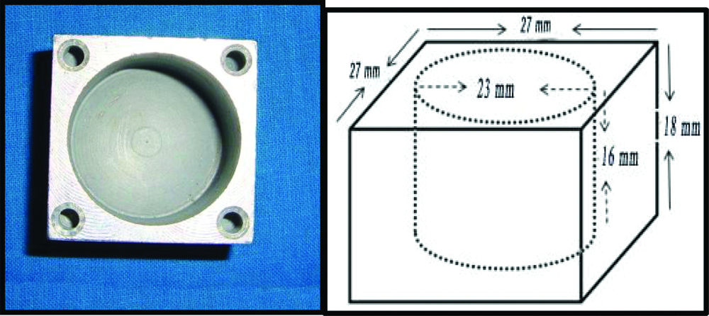
Twenty stainless steel blocks of dimensions 27×27×18 mm with a cylindrical mould space of diameter 23 mm and depth of 16 mm were custom-made. Four holes each with a diameter of 3 mm and depth of 2 mm were drilled at the four corners of each block to act as reorientation guides [Table/Fig-2]. Twenty titanium implants with standard platform, internal hexagon, tapered, 3.75 diameters, 10 mm length (ADIN Dental Implants, Israel) were used.
Custom-made stainless block.
Line diagram of custom-made stainless steel block.
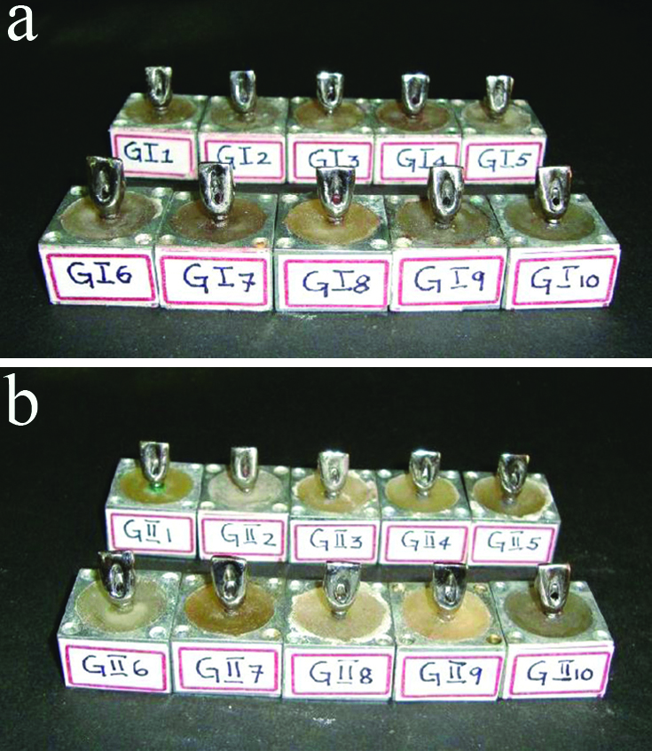
Each of the 10 implants were connected to one premachined titanium 25° angled abutment (ADIN Dental Implants, Israel) by hand torqueing the abutment screw with a hex driver (ADIN Dental Implants, Israel). Custom-made stainless steel block was selected and placed on the surveying platform of a dental surveyor. The angled abutment connected to the implant was attached to the surveying mandrel and positioned in the centre of the mould space of the custom-made stainless steel block such that the implant was submerged completely in the mould space, except for 1 mm at the crest module. Autopolymerising clear acrylic resin was mixed and poured into the mould space and then allowed to polymerise. This procedure was repeated to obtain 10 stainless steel blocks. These 10 implant-abutment assemblies secured in the stainless steel blocks were categorised as Group I [Table/Fig-3a].
(a). Group I test Samples; (b). Group II test Samples.
Milling of 25° angled premachined titanium abutments were done to standardise the abutment height, taper, mucosal collar thickness and to facilitate the access for the abutment screw channel. A total occlusal convergence of approximately 60 was given and the abutments were finished and polished. A total of 10 uniformly milled 25° angled premachined titanium abutments were obtained in this manner.
The custom cast cobalt chromium abutments were fabricated to match the shape and dimensions of the milled premachined abutments. An index was obtained of the milled abutment using addition polyvinylsiloxane impression material of putty and light body consistency in a single step procedure. The putty index thus obtained was used to standardise the dimensions of the custom cast abutments with that of premachined abutments. Following the retrieval of the putty index, the premachined abutment was unscrewed and removed from its implant.
One plastic abutment (ADIN Dental Implants, Israel) was then connected to the implant. Following the retrieval of the putty index; the premachined abutment was unscrewed and removed from its implant. The connected plastic abutment was then trimmed to the level of the abutment screw using a BP blade. Pattern resin was mixed and poured into the putty index previously obtained. The index was positioned over the trimmed plastic abutment. After setting, the index was removed with a single snap. In this manner the plastic abutment was customised similar to the shape and dimensions of the milled 25° angled premachined titanium abutment. The same protocol was followed to obtain 10 customised plastic abutment patterns of uniform dimensions which were ready for casting. Casting, divesting, and finishing of modified plastic abutment with Co-Cr alloy was done. Similar to the Group I samples, 25° angled custom cast cobalt chromium abutments were connected to the implants and the assembly was placed in the stainless steel block. These 10 implant-abutment assemblies secured in the stainless steel block were categorised as Group II [Table/Fig-3b].
After categorising the samples as Group I and Group II, cement-cum-screw retained Ni-Cr single crowns of uniform dimensions for each of the Group I and Group II abutments were fabricated. After the crowns were fabricated, Cementation of cement cum screw retained Ni-Cr cast crowns on the respective abutments was done with type I GIC cement.
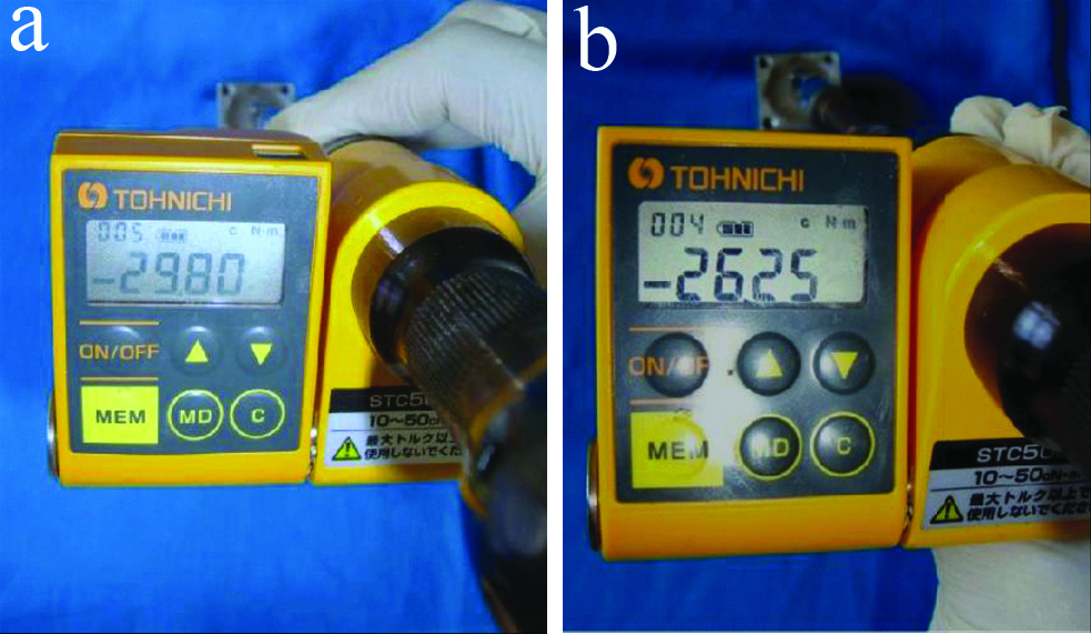
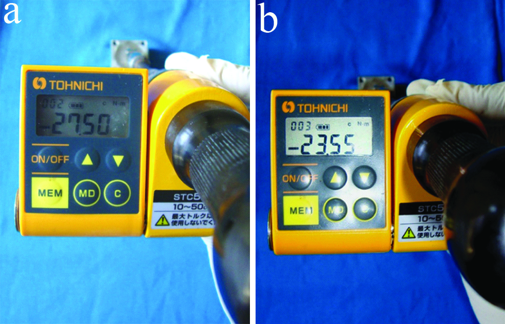
A 24 hours after the cementation of the crown, with the help of torque gauge, abutment screw was tightened to ≤35 Ncm. A 10 minute settling time was allowed, following which it was retightened to 35 Ncm to minimise embedment relaxation between the mating threads and to achieve the optimal “preload”. This procedure was repeated for all 10 samples. After a waiting period of 5 minutes, Reverse Torque Value (RTV) for each of the Group I test samples was measured individually using the digital torque meter This was designated as the pre-cyclic loading Reverse Torque Value (pre-RTV1) for that test sample. Similarly for the Group II test samples, the Reverse Torque Values were measured and designated as the pre-RTV2 [Table/Fig-4].
(a). Measurement of Reverse Torque Value before cyclic loading in Group I test sample; (b). Measurement of Reverse Torque Value before cyclic loading in Group II test sample.
Subsequent to the pre-RTV1 measurements, the abutment screws of all 10 Group I test samples were torqued to 35 Ncm and then retorqued after allowing a settling period of 10 minutes as described previously. The same procedure was followed for all 10 test samples of Group II.
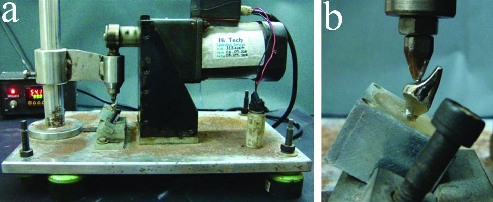
Cyclic loading was performed for all 20 test samples individually, with a custom-made cyclic loading machine to simulate oral loading conditions. The test sample with the cement cum screw retained cast restoration was placed in a custom-made positioning jig which positioned and secured the sample at a 30° angle to the floor to simulate the direction of forces at the maxillary anterior region [Table/Fig-5].
(a). Cyclic loading in custom made cyclic loading machine; (b). Cyclic loading at 30° angulation.
The test sample was subjected to cyclic loading. A sinusoidal waveform at 1.25 nHz for load up to 109 N (approximately) simulating human masticatory frequency and loads was applied [18]. This cycle was continued for 42 hours (2520 minutes with a break of 2 hours, every 21 hours) simulating 1,89,000 cycles which was approximately six months of function. The cyclic loading was performed in a dry environment. This procedure was repeated for all the 20 test samples. At the completion of the cyclic loading period, the Reverse Torque Value for each of the Group I and Group II test samples was measured with the digital torque meter. The post-cyclic loading reverse torque values of Group I and Group II samples were designated as post-RTV1 and post-RTV2, respectively [Table/Fig-6]. The RTD for each test group was then calculated (RTD=post-RTV(-)pre-RTV). The data thus obtained were subjected to statistical analysis.
(a). Measurement of Reverse Torque Value after cyclic loading in Group I test sample; (b) Measurement of Reverse Torque Value after cyclic loading in Group II test sample.
Statistical Analysis
The data obtained were tabulated using Microsoft Excel (Microsoft, USA) and SPSS (SPSS for Windows 10.0.5, SPSS Software Corp., Munich, Germany) software. Paired t-test was used to compare the mean pre and post RTV within both test groups. Independent t-test was used to compare the respective mean pre and post-cyclic loading reverse torque values and the respective mean reverse torque difference between both test groups.
Results
The mean pre-cyclic loading Reverse Torque Values of Group I test samples was 28.96 Ncm and mean post-cyclic loading Reverse Torque Values was 25.84 Ncm, the post-cyclic loading RTV was found to be significantly lesser then pre-cyclic loading RTV (p≤0.001) [Table/Fig-7]. The mean pre-cyclic loading Reverse Torque Values of Group II test samples was 26.01 Ncm and post-cyclic loading Reverse Torque Values was 23.82 Ncm, the post-cyclic loading RTV was found to be significantly lesser then pre-cyclic loading RTV (p≤0.001) [Table/Fig-8]. On comparison, the mean pre-cyclic loading Reverse Torque Values of Group I test samples (28.96 Ncm) was higher than that of Group II test samples (26.01 Ncm) and this difference was found to be statistically significant (p≤0.001) [Table/Fig-9].
Comparative evaluation of the mean pre and post-cyclic loading Reverse Torque Value of Group I test samples (25° angled premachined titanium abutments) using Paired t-test.
| Group I | Number of samples | Mean/SD RTV1 (Ncm) | p-value |
|---|
| Pre-cyclic loading (pre-RTV1) | 10 | 28.96±0.80 | 0.001 |
| Post-cyclic loading (post-RTV1) | 10 | 25.84±0.92 |
*p-value<0.001; significant at 1 level
Comparative evaluation of the mean pre and post-cyclic loading Reverse Torque Value of Group II test samples (25° angled custom cast cobalt chromium abutments) using Paired t-test.
| Group II | Number of samples | Mean/SD RTV2 (Ncm) | p-value |
|---|
| Pre-cyclic loading (pre-RTV2) | 10 | 26.01/±0.64 | 0.001 |
| Post-cyclic loading (post-RTV2) | 10 | 23.82/±0.63 |
*p-value<0.001; *significant at 1% level
Comparative evaluation of the mean pre-cyclic loading Reverse Torque Values of Group I test samples (25° angled premachined titanium abutments) (pre-RTV1) and Group II test samples (25° angled custom cast cobalt chromium abutments) (pre-RTV2) using Independent t-test.
| Group | Number of samples | Mean/SDPre-cyclic loading RTV (Ncm) | p-value |
|---|
| I (pre-RTV1) | 10 | 28.96/±0.80 | 0.001 |
| II (pre-RTV2) | 10 | 26.01/±0.64 |
*p-value<0.001; * significant at 1% level
On comparison, the mean post-cyclic loading Reverse Torque Values of Group I test samples (25.84 Ncm) was higher than that of Group II test samples (23.82 Ncm) and this difference was found to be statistically significant (p≤0.001) [Table/Fig-10]. On comparison, the mean RTD of Group I test samples: (-3.117 Ncm) was significantly higher than that of Group II test samples (RTD2), (-2.17 Ncm) and this difference was found to be statistically significant (p≤0.001) [Table/Fig-11].
Comparative evaluation of the mean post-cyclic loading Reverse Torque Values of Group Itest samples (25° angled premachined titanium abutments) (post-RTV1) and Group II test samples (25° angled custom cast cobalt chromium abutments) (post-RTV2) using Independent t-test.
| Group | Number of samples | Mean/SD Post-cyclic loading RTV (Ncm) | p-value |
|---|
| I (post-RTV1) | 10 | 25.84/±0.92 | 0.001 |
| II (post-RTV2) | 10 | 23.82/±0.63 |
*p-value<0.001; * significant at 1% level
Comparative evaluation of the mean Reverse Torque Difference values of Group I test samples (25° angled premachined titanium abutments) (RTD1) and Group II test samples (25° angled custom cast cobalt chromium abutments) (RTD2) using Independent t-test.
| Group | Number of samples | Mean/SD RTH (Ncm) | p-value |
|---|
| I (RTD1) | 10 | -3.11/±0.548 | 0.001 |
| II (RTD2) | 10 | -2.17/±0.757 |
*p-value<0.001; * significant at 1% level
Discussion
Implant supported prostheses for replacing missing anterior teeth are an established treatment option with favourable success and patient acceptance rates, that are available to us today [22]. Two piece dental implants are more popular than the single piece implant system owing to their versatility in various clinical situations [20].
The abutment screw is responsible for two opposite tasks. One, the screw needs to be firmly fixed to withstand loading. Two, it also needs to be retrievable for servicing and/or replacement of components above the fixture and hence, needs to be loosened [10]. There are two major aims for tightening screwed joints in the implant system. First, the joint components must be clamped together by applying a recommended torque on the joint screw which is achieved by applying an optimum preload. Second, the screw’s fatigue life should be prolonged. The screw loosens only if the external “joint separating forces” are greater than the forces keeping them together. Hence, the two primary factors involved in keeping implant screws tight are maximising the clamping force and minimising the joint separating forces [10].
Ideally, implants should be placed parallel to adjacent teeth and to the adjacent implant(s) and hence should be aligned vertically. But the morphology of existing bone in the premaxillary region often dictates that implants should be placed at an angle [12,23]. These implants are difficult to restore with conventional abutments and so in these situations these are restored using angled abutments to fulfill functional as well as aesthetic requirements. A variety of pre-angled titanium abutments are available at angulations ranging from 0° to 45° [24].
Angulated abutments are used in cases of non-ideal positioning of implants; they are more vulnerable to non-axial forces that transfer unfavourable forces to implant and bone thereby, compromising the prognosis of the treatment [22,23].
Some of the photo elastic and 3-D finite element studies have shown the greater degrees of stress patterns in the bone around the implants placed in the anterior maxilla when restored with angled abutments [13,25-27]. There have been limited studies comparing the influence of varying abutment angulations on screw loosening before and after cyclic loading. Studies comparing the screw loosening of premachined and custom cast angled abutments before and after cyclic loading in single implant situations in the anterior maxilla are lacking. All the steps discussed in the methodology for sample preparation and cyclic loading were performed by a single operator to avoid operator based errors and bias. Sterile, titanium dental implants of the same dimensions with an internal hexagon design were employed for standardisation of the implant fixtures. The internal hexagon configuration has a reported advantage of reduced vertical height from implant platform to the top of the abutment, distribution of lateral loading deep within the implant leading to a better-shielded abutment screw and long internal wall engagement that creates a stiff, unified body to resist joint micro movement when compared to external hexagon connection implant systems [2,17].
A single abutment angulation of 25° was selected for both test groups simulating clinical situation with angled placement of implants. A 25° angled premachined titanium abutments were chosen for Group I test samples (n=10). For Group II test samples, cobalt chromium alloy was used as material of choice for fabricating custom cast abutments (n=10), since the alloy has good mechanical properties. Both the premachined angled titanium as well as the plastic abutments used for casting were from the same manufacturer as that of the implant, to avoid the potential impact of interchangeably used abutments of other systems on screw loosening [21].
Implant-abutment assembly positioning was standardised using dental surveyor. Autopolymerising methyl methacrylate resin was used for embedding the implants in stainless steel blocks, as it exhibits an elastic modulus similar to that reported for trabecular bone (1.95 Gpa) [19]. The entire implant was submerged except for 1 mm at the crest module to allow easy visualisation.
Milling of the premachined abutments was done for standardisation of abutment height, taper, mucosal collar thickness. A cement-cum-screw retained maxillary central incisor restoration cast in Ni-Cr alloy, fabricated with an over contoured cingulum area was done to accommodate the stylus of the cyclic loading apparatus. A cement-cum-screw retained crown was chosen in the present study because it combines the ‘passivity’ feature of cement-retained prostheses along with the ‘retrievability’ feature of a screw retained prostheses and provides an aesthetic restoration in the anterior region [3,28]. All the 20 cast crowns were luted with the help of glass ionomer Type I luting cement, since this is one of the recommended luting agents for these types of restorations [29,30].
Following cementation, torque tightening of the abutment screws was done based on the protocol as recommended in the literature [6,11]. Mechanical torque gauges should be used instead of hand drivers to ensure consistent tightening of implant components to torque values recommended by implant manufacturers. A cyclic loading test was performed to simulate the components in function.
A cyclic load between 0 to 109 N was applied at a loading rate of 1.25 Hz to simulate the force acting on anterior teeth. Mechanical failures like screw loosening tend to occur early, usually with in the first month of function and hence, a six month simulation of loading was considered sufficient for the present study [19]. Non-axial forces were applied at a 30° inclination to the crown to simulate the functional stresses along the central incisor root angulation, which arise due to its aesthetic and functional requirements. This was achieved by the custom fabricated positioning jig. Tightened abutment screws undergo some relaxation resulting in loss of preload even without loading [19].
Studies regarding loss of preload in tightened abutment screws for premachined and custom cast straight abutments were carried out [31]. They reported a significant loss of preload in the custom cast abutments irrespective of the type of alloy, compared to the premachined titanium abutments. This is inline with the results obtained in the present study, where there is significant loss of preload even before cyclic loading for the custom cast abutments compared to the premachined abutments.
Studies regarding the effects of cyclic loading on abutment screw loosening by comparing between straight and 17° angled premachined titanium abutments, straight and 25° angled premachined titanium abutments and straight premachined and custom cast abutments, respectively for both internal and external connections were carried out [4,23,32]. They concluded that irrespective of whether the connection was internal or external there is a significant decrease in the reverse torque value after cyclic loading within each abutment type. This decrease has been attributed to settling effect which is otherwise called “embedment relaxation”, which occurs when the rough contacting spots flatten under load.
A similar study conducted on screw loosening, observed the abutment mating surfaces under Scanning Electron Microscope for interpretation of screw loosening results and suggested that the casting procedures render the abutment mating surfaces irregular compared to that of the premachined abutments [31]. This could be a reason for the significantly greater loss of preload seen in the custom cast abutment group in the present study and needs further evaluation.
The Reverse Torque Difference between the two groups was compared. Reverse torque difference is the difference between pre-cyclic loading reverse torque value and the post-cyclic loading reverse torque value. The value was calculated to assess the range of torque loss in Group I and Group II samples thereby to quantify the screw loosening. Custom cast abutments had significantly lesser reverse torque difference between pre and post-cyclic loading reverse torque values. This indicated that the range of torque loss was significantly greater for the premachined abutments as compared to the custom cast abutments. However, this could also be due to the limited sample size, employed in the present study. An increased sample size could also give different interpretations. This needs to be investigated further in future studies.
With in the limitations of the present study, both premachined and custom cast angled abutments had a significant loss in preload before cyclic loading. After cyclic loading custom cast angled cobalt chromium abutments showed significantly greater preload loss than the premachined angled titanium abutments. This loss in preload is indicative of abutment screw loosening. Thus, the null hypothesis was rejected because of the significant differences in screw loosening values between both test groups.
Limitation
The present study had some limitations. The duration of cyclic loading was only a six month simulation performed under dry conditions. A longer loading period may affect the screw joint differently. A reduced magnitude of torque that loosens abutment screws may not be detrimental to the screw joint unless it is progressive and if the remaining preload is sufficient to prevent slippage of joint components [4]. This can be assessed when longer loading periods are employed. Further, the presence of moisture in the oral cavity may also impact the results differently. Accurately simulating the normal human functional parameters in in-vitro studies is both time consuming and technically challenging.
Future studies incorporating higher sample sizes with a longer loading duration and simulating the oral environment are recommended to enhance the results obtained in the present study.
Conclusion
There was loss of preload for both Groups I and II samples against the applied tightening torque before cyclic loading as exhibited by the mean pre-RTV1 and pre-RTV2 respectively. The mean post-cyclic loading Reverse Torque Values of abutment screws for both Groups I and II test samples were significantly lesser than their respective mean pre-cyclic loading Reverse Torque Values indicating that screw loosening occurs after cyclic loading for both premachined as well as custom cast angled abutments. On comparison between the two abutment types, the mean Reverse Torque Value of abutment screws for Group II was significantly lesser than that of abutment screws of Group I, after cyclic loading indicating greater screw loosening for custom cast angled abutments than the premachined titanium angled abutments.
*p-value<0.001; significant at 1 level
*p-value<0.001; *significant at 1% level
*p-value<0.001; * significant at 1% level
*p-value<0.001; * significant at 1% level
*p-value<0.001; * significant at 1% level