Orthodontic force leads to tooth movement which occurs by remodelling changes in PDL, alveolar bone, and gingiva leading to macroscopic and microscopic changes of varying degrees of magnitude [1]. There are two types of tooth movement, Physiological tooth movement and Orthodontic Tooth Movement (OTM). The strains caused due to the applied force leads to change in the vascularity leading to production of various inflammatory mediators that result in bone remodelling by deposition and resorption [2].
The amount and type of displacement is determined by the loading regime as well as by orthodontic force magnitude. Usually a force of 1.5 N (approximately 150 gm) is required for the closure of the midline diastema according to Profit WR [3]. The presence of the PDL makes direct application of force to the tooth more complex as it acts as a shock absorber [4].
There are two main theories that explain the tissue reaction when orthodontic force is applied to the teeth i.e., the ‘Pressure–Tension’ theory, and the ‘Bioelectric’ theory [5,6]. Currently, the cellular reaction of the alveolar bone has been perceived as a reflection of the local state of loading. A way to verify the validity of these theories is to investigate the stress and strain distributions within the whole periodontium following the application of orthodontic forces [6].
A midline diastema seen during permanent dentition stage is not self-corrective and needs orthodontic intervention after careful diagnosis of its aetiology [7]. Fixed orthodontic appliances can provide better control on the crown and root angulation, allowing proper correction of the diastema than removable appliances that cause tipping movement of the roots leading to high relapse tendency. Maxillary midline diastemas have high relapse tendency needing permanent retention [8]. There is varying degree of stresses and strains that the alveolar bone is subjected to, during the treatment of midline diastema. As direct measurement of these parameters is almost impossible, FEM is an effective method for calculating stress and strain in the alveolar bone.
The FEM has proved to be a valid and reliable technique for the calculation of the local state of deformation and loading characteristics of complex structures. No study has been done to calculate the stresses and the strains that the maxillary central incisors are subjected to, during closure of the diastema. Though in the literature 1.5 N (approximately 150 gm) of force is the ideal force required for closure of the midline diastema, in this study we have assessed if the stresses and strains around the incisors vary when the width of the diastema increases but the forces applied are the same. Thus, the purpose of this study was to assess the stress and the strain around these incisors during closure of the diastema.
Materials and Methods
In this present finite element analysis, a CBCT scan of anterior region of maxilla of a patient exhibiting midline diastema was taken from the archives of Department of Orthodontics and Dentofacial Orthopedics, Faculty of Dental Sciences, Ramaiah University of Applied Sciences, Bengaluru, Karnataka, India. Using the MIMICS 8.11 version software, three, 3-D models having varying midline diastema width of 4 mm, 3 mm and 2 mm were constructed as shown in [Table/Fig-1,2]. These constructed 3-D models of the maxillary anterior dentition contained cortical bone, spongy bone and canine to canine teeth with adjusted edgewise Mclaughlin, Bennett, and Trevisi (MBT) 0.022’’ slot bracket on the labial surface and a 0.019×0.025” orthodontic stainless steel wire engaged in the MBT slot.
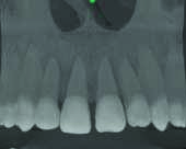
Panoramic view of CBCT showing anterior region of maxilla with midline diastema.
Models with varying midline diastema width and meshed model.
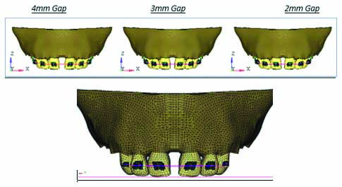
Hypermesh version 13.0 software was used for meshing [Table/Fig-2]. Total number of nodes were 34445 and total number of elements were 183234. Material Properties of the materials used were assigned as shown in [Table/Fig-3] [9]. All the nodes at the distal surface area of the models were restricted from displacements as the boundary condition.
Material Properties of the materials used.
| Young’s Modulus (MPa) | Poisson’s Ratio |
|---|
| Tooth | 20300 | 0.26 |
| PDL | 0.667 | 0.49 |
| Cancellous bone | 13400 | 0.38 |
| Cortical bone | 34000 | 0.26 |
| SS bracket | 200000 | 0.25 |
| Stainless steel | 160000 | 0.3 |
A 1.5 N of force was applied towards the midline on all the brackets leading to closure of midline diastema by mesial movement of all the anterior teeth that is considered as ideal for closure of the midline diastema [2]. The anterior segment was considered as a combined single unit. This was done as usually in clinical scenario; all the teeth together will be considered for closure of diastema (i.e., elastomeric chain will be engaged in all the anterior teeth).
The resultant stresses and strain caused by these forces on the alveolar bone around the central incisors from the crest to the root apex was calculated using ANSYS 12.1 version software.
Results
The stress and strain seen in the different models with varying width of midline diastema in cortical bone and cancellous bone [Table/Fig-4].
Stresses and strain seen in the different models with varying width of midline diastemain cortical bone.
| Midline diastema width | Maximum Von-Mises Stress Contours | Maximum principle Stress Contours | Maximum Von-Mises Strains Contours |
|---|
| Cortical bone | Cancellous bone | Cortical bone | Cancellous bone | Cortical bone | Cancellous bone |
|---|
| 2 mm | 7.16 MPa | 2.68 MPa | 2.10 Mpa | 1.75 MPa | 5.24 e-4 | 1.97 e-3 |
| 3 mm | 6.34 MPa | 2.7 MPa | 2.21 MPa | 1.79 MPa | 4.63 e-4 | 2.00 e-3 |
| 4 mm | 5.67 MPa | 2.73 MPa | 2.27 MPa | 1.84 MPa | 4.14 e-4 | 2.01 e-3 |
Note: - e is scientific format of representing smaller values e=0.00201
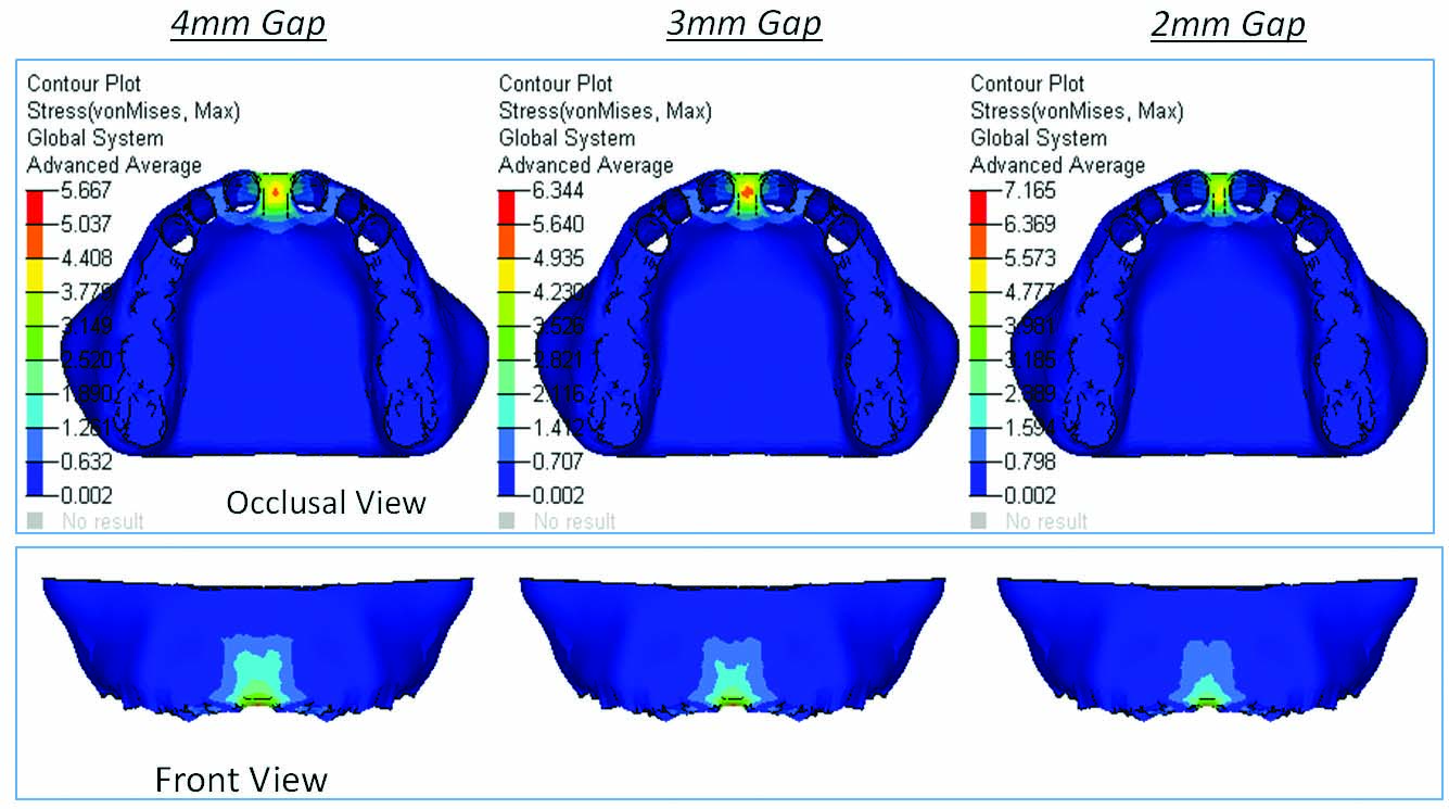
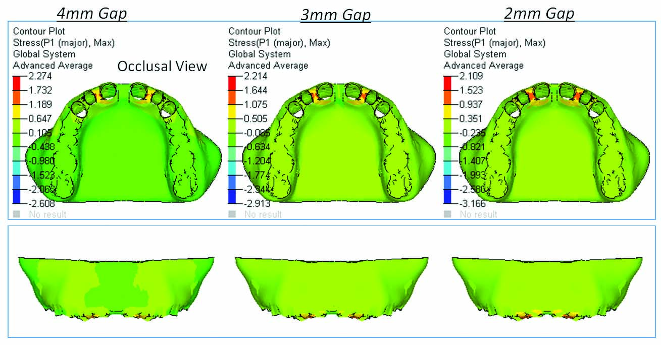
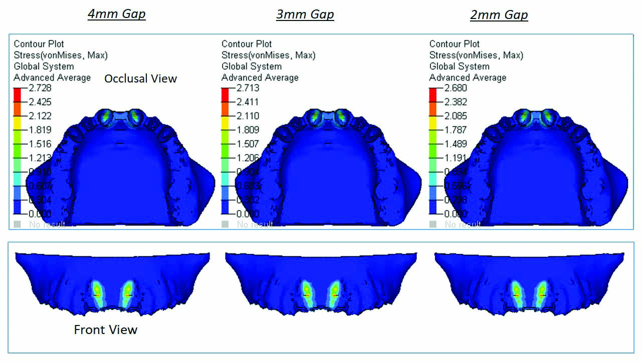
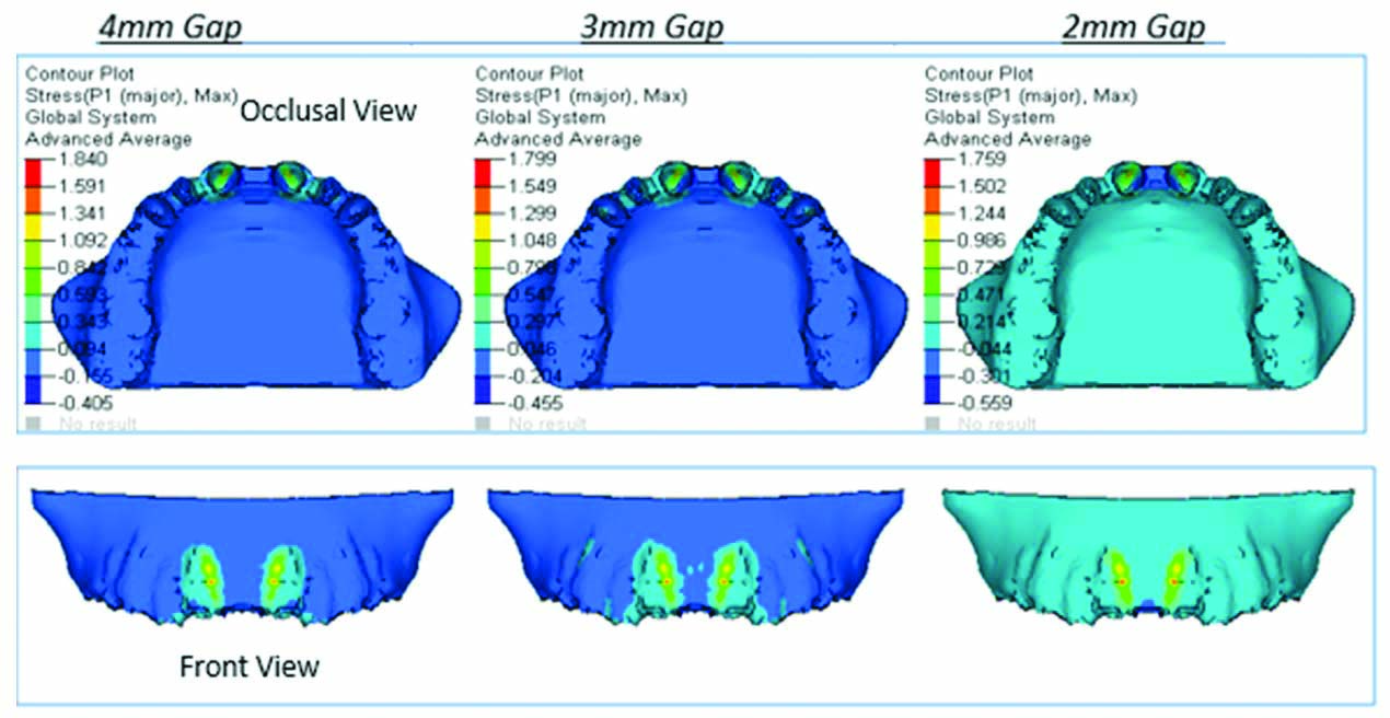
In the cortical bone maximum compressive stress (Von-Mises stress) was observed between central incisors as shown in [Table/Fig-5] and maximum tensile stress (principle stress) was observed between central incisor and lateral incisor as shown in [Table/Fig-6]. Maximum strain in the cortical bone was observed between central incisors close to the crest of the alveolar bone as shown in [Table/Fig-7].
Maximum Von-Mises stress observed between central incisors in cortical bone.
Principle stress contours in cortical bone (mm) i.e., maximum stress observed between central incisor and lateral incisor.
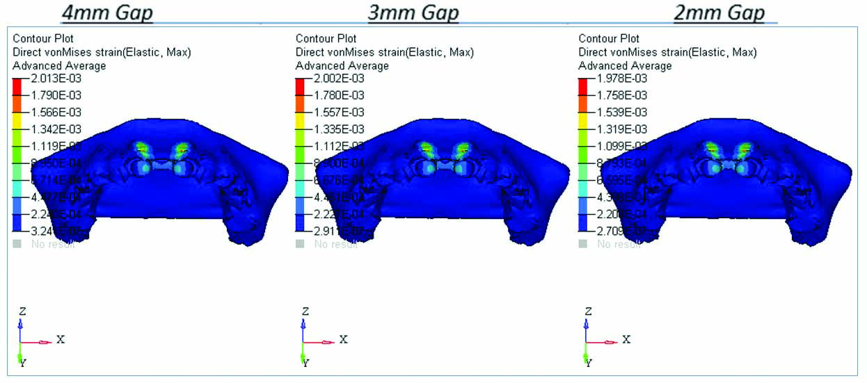
Von-Mises Strains Contours in Cortical bone (mm/mm) observed between central incisors.
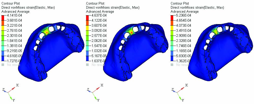
In the cancellous bone maximum compressive stress (Von-Mises stress) was observed between the central incisor segment of bone as shown in [Table/Fig-8] depicted by the red section between the two central incisors and maximum tensile stress (principle stress) was observed along the roots of central incisor cavity, near the middle third of the root cavity as shown in [Table/Fig-9]. Maximum strain in the cancellous bone was observed along the root cavity of central incisors as shown in [Table/Fig-10].
Von-Mises Stress Contours in Cancellous bone (mm).
Principle stress contours in cancellous bone (mm).
Von-mises strains contours in cancellous bone (mm/mm). Maximum strains are observed along the root cavity of central incisors.
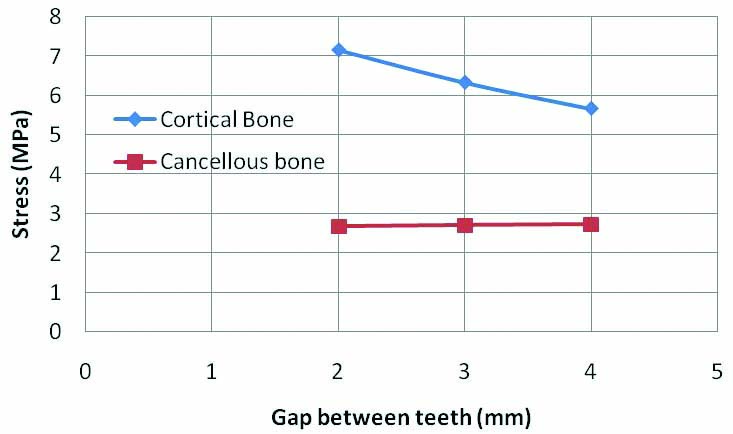
From the graph, it can be inferred that the stresses in cortical bone increases with decrease in the midline diastema width. However stresses remain constant for cancellous bone with the increase in midline diastema width as shown in [Table/Fig-11].
Graphical representation of stress variation in bone for various diastema gap between the teeth in cortical and cancellous bone.
In the longitudinal section or the frontal view in both the cortical and cancellous bone, stress concentration was more near the cervical region (near the crest of the alveolar bone) of the teeth with midline diastema width of 2 mm than in the other models as shown in [Table/Fig-12]. In all the 3 models it was seen that the stresses gradually decreased as they neared the apex of the tooth.
Graphical representation of longitudinal stress and strain variation in bone from crest of alveolar bone (includes both cortical and cancellous bone) to root apex for various diastema gap between the teeth.
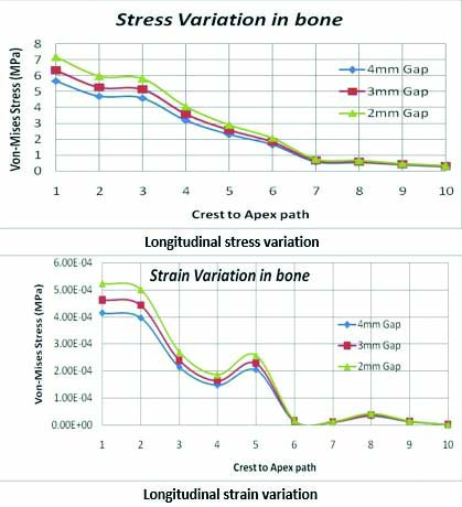
Similarly, strains were also high in the model with midline diastema width of 2 mm and were concentrated more in the cervical region of the teeth as shown in [Table/Fig-12]. In all the 3 models it was seen that the strain gradually decreased as it reached the region 4 mm from the cervical region. The strain again increased at 5 mm gradually decreasing as they reached the apex of the tooth in all the 3 models [Table/Fig-12].
Discussion
Orthodontic tooth movement occurs as a result of a force being applied to a tooth. When the force is applied to the crown of the tooth, initial tipping occurs followed by bodily movement of the tooth. Bodily movement of the central incisors to close the diastema is beneficial as it gives more stability in long-term retention of the closed space.
In this study, we have assessed if the stresses and strains around the incisors vary when the width of the diastema increases but the forces applied remains constant. Thus, we found that stresses in the cortical bone were more towards the cervical region whereas in the cancellous bone stresses were more towards the middle of the tooth in all the three models. In the longitudinal section stress and strain was more concentrated at the cervical region gradually decreasing as they reached apex of the tooth in cortical bone and in the cancellous bone maximum stress was observed in the middle third.
Stress in alveolar bone: According to Jones ML et al., when an orthodontic force is applied, stresses usually occur at the cervical margin (the neck of tooth at the junction between crown and root) [10]. This was in accordance with our study where similar results were obtained.
According to Jing Y et al., the highest stresses in the alveolar bone were found at the cervical third and the apical third [11]. Translation is better for periodontal tissue than tipping movement as uniform stress distribution is produced in the former.
Similar results were obtained in a study done by Fongsamootr T et al., where they measured stress distributions and displacement over the tooth and bone structure simulated by Finite Element Analysis [12]. They found that for the cortical bone, the highest stresses were concentrated around the cervical area.
The study done by Dalstra M et al., concluded that the surface of the alveolar bone is not smooth and therefore, when force is applied on the tooth it leads to high stress and strain distribution [13].
The study done by Choy K et al., concluded that stress distribution along the root, decreases when there is an increase in the root taper, increase in alveolar bone loss and increase in apical root resorption [14].
In a study done by Viecilli RF et al., it was stated that it is possible to have coexisting compression and tension areas in different directions in the dento-alveolar structures, such as in the bone, as these stresses are three-dimensional and not purely hydrostatic [15]. This finding is similar with the findings of Geramy A et al., where they found that the stress and strain usually follow a similar pattern [9]. Thus, it is wrong to refer to orthodontic stresses simply as “pressure” or to carry out simplified 1-D calculations taking force and root surface area into account. This requires 3D modelling. This is the reason FEM 3D modelling was undertaken in our study.
In a study done by Kumar JB et al., they found that the stresses in the alveolar bone was very low near the apex of the root [16]. This is similar to study done by Li P et al., to calculate the mechanical stress on root from orthodontic tooth movement by sliding mechanics, in which they found that the highest stress concentration in the roots was always localised at the cervical margin and the stress distribution was less concentrated at the apical region [17].
In a study done by Fariba S et al., it was found that when force to move the tooth bodily is applied, the stresses that are produced can be either tensile or compressive. The amount and type of stress concentration varied from cervical to apex region of the tooth. More stress concentration was observed at the cervical levels and not at the apex [18]. For this reason, resorption may be more at cervical sites than other sites. These findings were also in accordance with our study. The longitudinal graphical representation of stresses in the bone showed maximum stress near the cervical area that reduced near the apex in cortical bone while in the cancellous bone it was more near the middle third.
Strains in alveolar bone: According to a study done by McCormack SW et al., they found that the strain concentration in the alveolar bone was highest towards top of the tooth socket and then gradually decrease towards the apex [19]. They also found that strain results obtained in the alveolar bone were not smooth but rather contained fluctuating values. According to Verna C et al., the highest strain occurred in cervical region while in the apical region the strains were relatively low [20].
Similarly according to Shantavasinkul P et al., peak strains occur closest to the site of application of force and gradually dissipate with increasing distance [21]. These results are similar to the result we got in our study, where the strain was mostly seen near cervical region near the point of force application and reduced near the apex. In our study, strain gradually decreased as it reached the region 4 mm from the cervical region. The strains again increased at 5 mm gradually decreasing as they reached the apex of the tooth in all the three models. The maximum strain in the cortical bone was 5.24 e-4 for 2 mm midline diastema width model, while in the cancellous bone it was 2.01 e-3 for 4mm midline diastema width model.
Thus, it can be concluded that to avoid increased stress and strain loading on the central incisors when the width of the diastema is less, appropriate modification and controlled low forces need to be applied.
Limitation
The limitation of this study is that only linear properties of the materials were taken into consideration. The property of PDL being anisotropic was excluded from this study. Further work can be done taking into account the non-linear properties of the PDL and also full arch can be modelled for in depth evaluation.
Conclusion
It can be concluded that, von mises stresses increases as the width of diastema decreases in the cortical bone. The stresses in cancellous bone remains constant in all the three models as there are minor variations in all the three models.
In the longitudinal section, stress and strain was more concentrated at the cervical region gradually decreasing as they reached apex of the tooth in cortical bone and in the cancellous bone maximum stress was observed in the middle third.
Thus, low forces need to be applied to the central incisors during midline diastema closure taking into account the width of the midline diastema.
Note: - e is scientific format of representing smaller values e=0.00201