Introduction
Class III malocclusion exists when the mandibular molar occludes mesial to the maxillary molar as a result of a skeletal discrepancy i.e., normal maxilla and protruded mandible, retruded maxilla and a normal mandible or a retruded maxilla and a protruded mandible, concomitant with or without a dental discrepancy, or due to the functional shift of the mandible. Orthopaedic and functional appliances like chin cup, Functional Regulator 3 (FR3), Class III activator, reverse twin block etc., can be used to treat Class III malocclusion. Reverse twin block is a patient friendly appliance, presenting acceptable clinical results. Stresses are the key to remodelling of the alveolar and craniofacial bones incident to functional and orthopaedic forces, which can be elucidated via Finite Element Analysis (FEA). Literature lacks studies pertaining to biomechanical evidence on the functional appliance effect in Class III malocclusion.
Aim
To evaluate the patterns of stress distribution and displacement in the maxilla and the mandible with the reverse twin block appliance, in four groups with combinations of bite force of 107 N and without bite force, along with passive tension of 1.27 N and 1.47 N for 2 mm and 4 mm interincisal clearance respectively, through FEA.
Materials and Methods
A three dimensional finite element model was developed from the Cone Beam Computed Tomography (CBCT) images of a patient with Class III malocclusion using Hypermesh 13.0 software. The model simulated forces of reverse twin block appliance with 2 mm and 4 mm interincisal clearance with and without maximum bite force of 107 N. Stress distribution and displacement in the region of glenoid fossa, maxillary tuberosity, Anterior Nasal Spine (ANS), neck of the condyle and gonial region was studied.
Results
Maximum stresses were observed in the glenoid fossa and the neck of the condyle. Stress generation was subsequently more with 4 mm interincisal clearance group. The displacement resulting from reverse twin block was mainly dentoalveolar. Maxillary incisors displaced more than the mandibular incisors. The mandible displaced more in the forward and downward direction.
Conclusion
The treatment outcomes with reverse twin block appliance previously assessed by means of cephalometric studies were validated with insight of stresses induced at different regions of the maxilla and the mandible via the finite element methodology. The forces exerted by this appliance directed the stresses more towards the dentoalveolar region. Stresses were more profound when the passive tension was concurrent with the bite force.
Introduction
Class III malocclusion was described by Angle EH as one in which the relative position of the mandibular first molar is mesial to that of the maxillary first molar in patients with a normal maxilla and protruded mandible, or a retruded maxilla and normal mandible or a combination of retruded maxilla and protruded mandible. A patient with a normal maxillomandibular relationship can also present with a Class III dental relationship. They usually have a concave facial profile with a protrusive lower lip [1]. It is seen in nearly 5% of American population and around 4% to 13% of Asian population show the signs mainly due to deficiency of the midface. The incidence of Class III malocclusion is slightly higher among the Japanese and Chinese population, however, African-American population shows a lesser incidence [2-6].
The literature describes different orthodontic and orthopaedic treatment approaches to the treatment of skeletal Class III malocclusion, which are used according to the pattern of malocclusion, clinician’s experience in their use, patient compliance and the skeletal age of the patient. For growing patients with skeletal issues, intraoral and extraoral appliances, such as the removable mandibular retractor, FR3, bionator, Facemask (FM), chin cup, reverse twin block or double piece corrector are indicated [7].
The twin block appliance is widely used for the treatment of Class II malocclusion. Another version of twin block has been advocated by Clark W for the treatment of Class III malocclusion, the reverse twin block. Twin blocks are considered to be aesthetic, effective and comfortable. Thereby satisfying the patient as well as the operator and being one of the patient friendly functional appliances [8].
FR 3 described by Frankel, is the most commonly used appliance for Class III malocclusion. Its mode of action is by eliminating the factors that hinder the growth of the maxilla and prevent the development of the mandible [9]. This is similar to the proposed mode of action of the Class III Twin Block. According to Clark W, reversing the angulation of the inclined planes of a twin block, harnesses the occlusal forces. The occlusal blocks are placed over the upper deciduous molars/premolars and the lower first molars with the reversed occlusal inclined planes cut at a 70° angle. This acts as a functional mechanism for correction of the interarch relationships by advancing the maxilla while the mandible serves as an anchorage unit. Hence, reverse twin block aids in correction of Class III malocclusion [Table/Fig-1]. Clark suggested construction of reverse twin block in maximum retrusive position and an interincisal clearance of 2 mm and 4 mm in mesofacial and brachyfacial types respectively [8,10]. The occlusal forces that are incident on the blocks constitute the major proprioceptive stimulus for growth. Parle D et al., evaluated the maximum bite force in Class I jaw bases and Class III jaw bases to be 104.7 N and 109.3 N respectively [11]. Furthermore, the role muscles have been well postulated in functional appliance therapy. Andresen V and Haupl K suggested that cellular and tissue reactions induce bone remodelling for tooth movement via the active contraction of jaw muscles that is produced by a functional appliance [12]. Harvold and Woodside indicated that the functional appliances induce forces by passive tension of muscles associated with the viscoelasticity of soft tissues [13]. A study conducted by Noro T et al., evaluated if the forces are generated by passive tension of soft tissues or active contraction of jaw muscles, or both. They concluded that passive tension has a longer duration of force and hence, plays a significant role rather than active contraction of muscles and calculated the passive tension in Class III group to be 1.27 N and 1.47 N at 2 mm and 4 mm interincisal clearance respectively [14].
Reverse twin block appliance.
To investigate the effects of functional and orthopaedic appliances, point by point stress and strain distribution should be determined. In order to elucidate biomechanical changes in the craniofacial complex, various studies involving photoelastic, strain gauge and holographic interference techniques have been conducted [15-18]. Whilst these approaches have provided some useful information, a precise evaluation of the displacements and stresses induced in living tissues has not been reported.
In the meantime, the study of stresses and strains in engineering was studied via the FEA. This made it possible to assess similar biomechanical effects induced by the external forces on the living structures as well. The first finite element model was homogeneous and isotropic and used average geometric relationships to describe the tooth bone structure two dimensionally [19]. Farah JW et al., subsequently introduced the three dimensional finite element model [20]. The Finite Element Method (FEM) can be applied to assess the biomechanical effect of several treatment modalities. It ultimately is an approximate method that represents the three dimensional stress distribution as well as the deformation in the bodies when forces are incident [21].
Literature describes studies that have elicited the treatment effect of orthopaedic and functional appliances for treatment of Class III malocclusion through cephalometrics [22-26]. Limited studies assess the stress distribution pattern in the craniofacial structures with the use of functional appliances in the treatment of Class III malocclusion [21,27,28]. Hence, the purpose of this study was to assess the stresses and displacement pattern on the maxilla and the mandible with the reverse twin block appliance through FEA with the following objectives.
To assess the Von Mises stress distribution and displacement on the mandible and the maxilla with reverse twin block appliance with 1.27 N force of passive tension with a 2 mm interincisal clearance.
To assess the Von Mises stress distribution and displacement on the mandible and the maxilla with reverse twin block appliance with 1.27 N force of passive tension along with maximum bite force of 107 N with a 2 mm interincisal clearance.
To assess the Von Mises stress distribution and displacement on the mandible and the maxilla with reverse twin block appliance with 1.47 N force of passive tension with a 4 mm interincisal clearance.
To assess the Von Mises stress distribution and displacement on the mandible and the maxilla with reverse twin block appliance with 1.47 N force of passive tension along with maximum bite force of 107 N with a 4 mm interincisal clearance.
To compare the Von Mises stresses in the maxilla and the mandible among the four groups.
Materials and Methods
The present study was conducted at the Department of Orthodontics and Dentofacial Orthopaedics, Faculty of Dental Sciences, Ramaiah University of Applied Sciences, Bangalore, India, using the FEA. The duration of the study was six months.
A CBCT scan of the skull of a patient with Class III malocclusion due to normal maxilla and prognathic mandible was selected from the archives. The sections obtained were in Digital Imaging and Communication of Medicine (DICOM) format and directly sent into the computer.
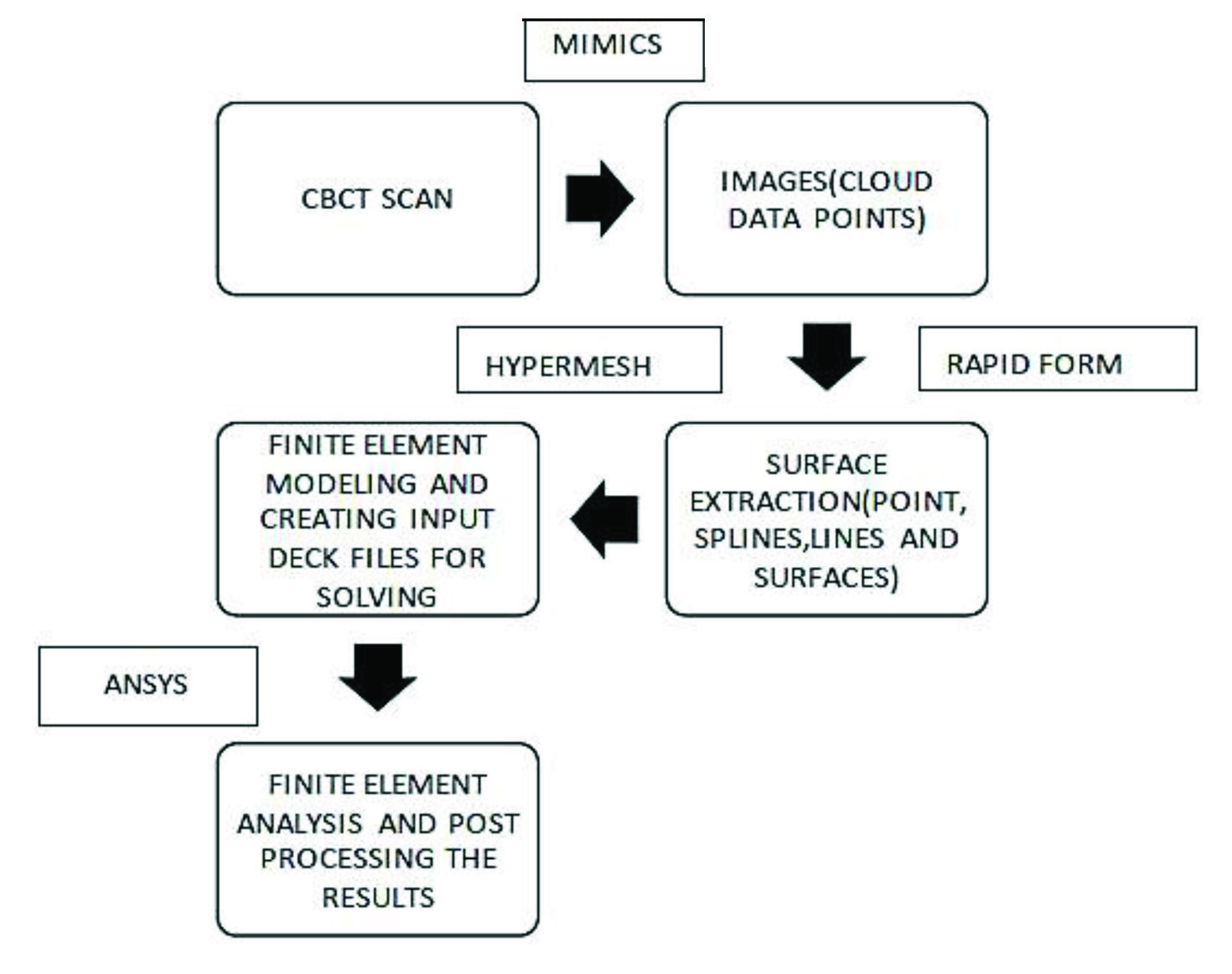
Steps involved in the Finite Element Analysis are [Table/Fig-2]:
General Flow chart of the complete methodology followed for Finite element study.
Generation of 3D geometric model.
Discretisation
Allocating material properties
Boundary conditions
Force application
Analysis and result interpretation
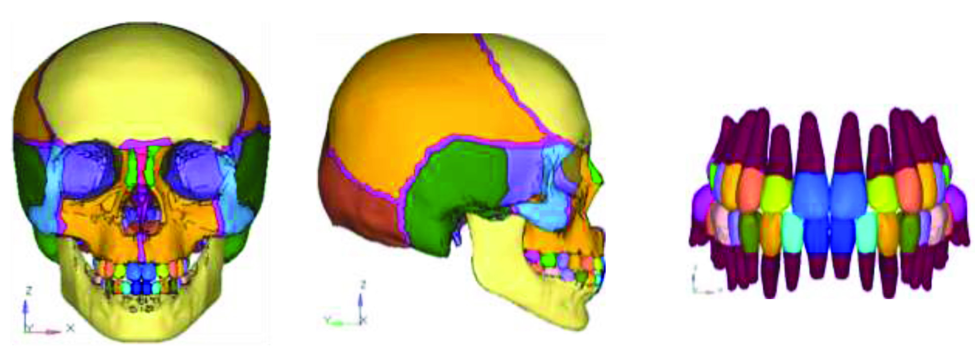
1. Generation of 3D geometric model using MIMICS: The aim was to produce a mathematical model, which represented the biological properties of the human skull and the reverse twin block appliance. This was represented in terms of points (grids), lines, surfaces (patterns) and volumes (hyperpatches). CBCT scan data of the skull was processed using MIMICS 8.11 software. The DICOM images of the CBCT scan were selected and converted into binary Stereolithography (STL) file format. The cross-sections of the skull, 961 in number, were obtained at equal intervals of 3 mm. Different bones of the skull were viewed accurately in each cross section. Further, this was converted into two geometric models consisting of surfaces and lines. Once the surface models were obtained, it was exported to FEM tool, HYPERMESH 13.0 [Table/Fig-3].
Geometric model of human skull and teeth.
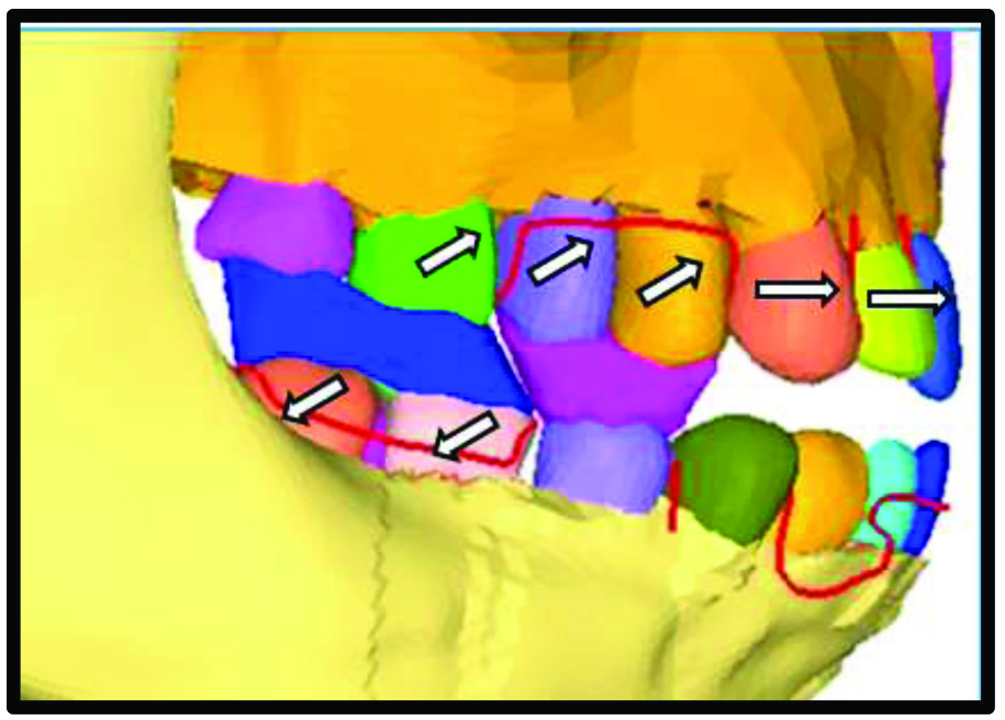
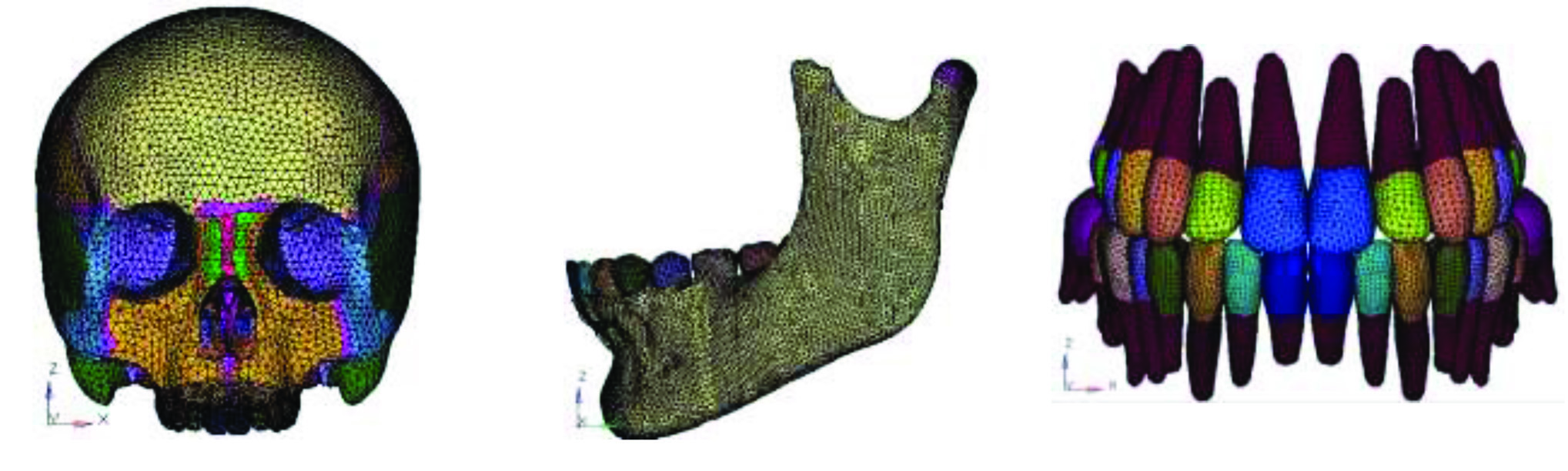
2. Conversion of 3D geometric model into finite element model/discretisation: The geometric models were further converted into Finite element models by using software called HYPERMESH version 13.0, which is a general purpose processor and supports many problem solvers like Nastran, ANSYS and LS-Dyna [29]. ANSYS version 12.1 was the solver used for the analysis of the present study. The model of the human skull was simulated and converted into a finite element model i.e., discretisation [Table/Fig-4]. Discretisation may simply be described as the process in which the given body is subdivided into an equivalent number of finite elements. This is done by connection of nodes and elements, which forms the finite element mesh. Using ANSYS version 12.1, the reverse twin block appliance was modelled. The reverse twin block constitutes an upper and lower component. The occlusal blocks placed over the upper premolars and the lower first molars with the occlusal inclines sectioned at an angulation of 70° [Table/Fig-5]. Two different models of the skull with reverse twin block in position were simulated i.e., 2 mm of interincisal clearance and 4 mm interincisal clearance. The models were fixed in the region of foramen magnum and discretised in X, Y and Z axis [Table/Fig-6].
Finite element mesh model of human skull and teeth.
Model of reverse twin block appliance with 70° angulation of the inclined planes.
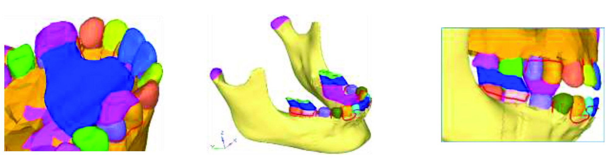
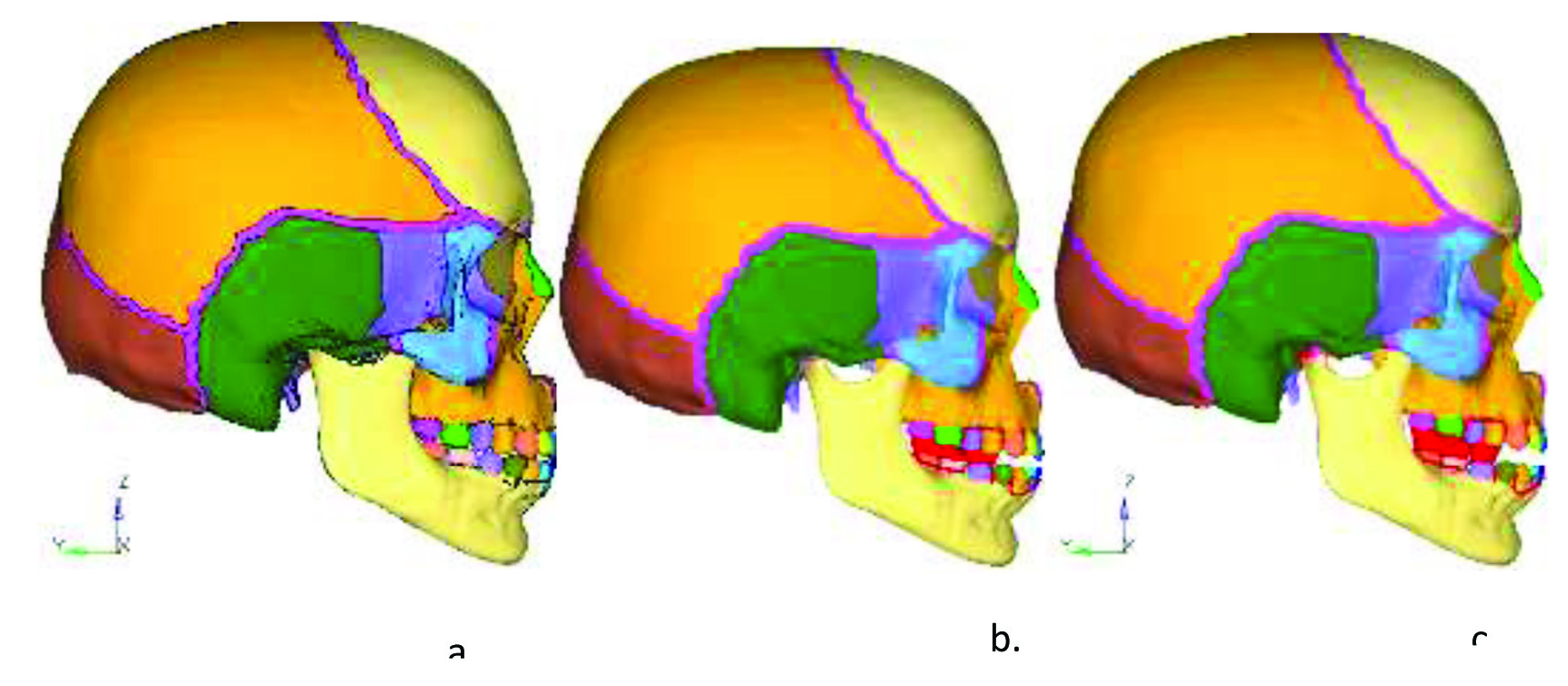
The initial position (a); with 2 mm Interincisal clearance (b); and 4 mm interincisal clearance (c).
3. Assigning material properties: The assignment of proper material properties to a finite element model is necessary to simulate the behaviour of the object studied. The different structures involved in this study were the tooth, periodontal ligament, cortical bone, cancellous bone and acrylic. The material properties assigned were the Young’s modulus (or modulus of elasticity) and the Poisson’s ratio and they were assumed to be isotropic and homogenous [Table/Fig-7]. The material properties used in this study were derived from previous studies [27,30-33].
Material properties used in the study.
| S No. | Material | Youngs modulus (GPA) | Poissons coefficient |
|---|
| 1. | Acrylic | 2.55 | 0.3 |
| 2. | Teeth | 20.29 | 0.3 |
| 3. | Periodontal ligament | 0.005 | 0.49 |
| 4. | Cortical bone | 14.5 | 0.323 |
| 5. | Cancellous bone | 1.37 | 0.3 |
4. Boundary conditions: The boundary conditions were defined to simulate how the model was constrained and to prevent it from free body motion. The nodes attached to the area of outer surface of foramen magnum were fixed in all directions to avoid free movement of the skull. The amount of stress and strain in the maxilla and the mandible were calculated at each nodal point using HYPERMESH and ANSYS for generating models and post processing the results respectively. The bone element was assumed to be homogenous. The appliance was assumed to be of pure acrylic.
Total number of nodes=90565
Total number of elements=390181
5. Application of forces: The reverse twin block appliance was placed as a two component assembly on the maxilla and the mandible. The upper occlusal blocks covering the premolars and the lower occlusal blocks covering the molars. The appliance assembly was considered bilaterally symmetrical. The two models simulated had an interincisal clearance of 2 mm and 4 mm respectively. A force of 1.27 N and 1.47 N was applied with and without the maximum bite force of 107 N, on the inclined plane of the reverse twin block.
6. Execution of analysis and interpretation of results: Four groups were formed for the purpose of the study [Table/Fig-8]. In each group, the forces were directed on the 70° angulated inclined plane. The amount of Von Mises stresses and maximum displacements generated in the region of glenoid fossa, maxillary tuberosity, ANS, the neck of the condyle and gonial region were calculated using combinations of passive tension and maximum bite force and represented on the colour band, with various colours representing different stress levels and displacement values.
| Group no. | Criteria |
|---|
| Group 1 | 1.27 N force of passive tension with a 2 mm interincisal clearance. |
| Group 2 | 1.27 N force of passive tension along with maximum bite force of 107 N with a 2 mm interincisal clearance. |
| Group 3 | 1.47 N force of passive tension with a 4 mm interincisal clearance. |
| Group 4 | 1.47 N force of passive tension along with maximum bite force of 107 N with a 4 mm interincisal clearance. |
Results
The results of FEA is known as post processing. After the construction of the models and load application, results were obtained.
When the reverse twin block appliance was placed on the maxilla and the mandible, with 1.27 N force of passive tension with a 2 mm interincisal clearance, the following results were seen [Table/Fig-9a].
Von Mises stresses (MPa) and displacement (mm) in the maxilla and the mandible.
1Negligible movement is observed
2Maxillary teeth moves more compared to mandibular teeth
3Negligible movement is observed
4Maxillary teeth move more compared to mandibular teeth
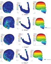
Stresses generated were maximum in the posterior aspect of glenoid fossa i.e., 1.8 MPa and the neck of the condyle i.e., 2.0 MPa and minimum in the region of maxillary tuberosity and ANS i.e., 0.9 MPa. The stress in the gonial region was 1.5 MPa. No stresses were seen on cervical aspect of maxillary premolars. No displacement was observed in the maxilla or the mandible.
When the reverse twin block appliance was placed on the maxilla and the mandible, with 1.27 N force of passive tension and maximum bite force of 107 N with a 2 mm interincisal clearance, the following results were seen [Table/Fig-9b].
Stresses generated were maximum in the glenoid fossa i.e., 23.6 MPa and the mandibular molars i.e., 25.3 MPa, followed by 19.7 MPa in the neck of the condyle and minimum in the region of maxillary tuberosity and ANS and cervical aspect of maxillary premolars i.e., 5.2 MPa. The stress in the gonial region was 5 MPa. Anterior displacement of maxillary teeth was more compared to mandibular teeth.
When the reverse twin block appliance was placed on the maxilla and the mandible, with 1.47 N force of passive tension with a 4 mm interincisal clearance, the following results were seen [Table/Fig-9c].
Stresses generated were maximum in the neck of the condyle i.e., 2.6 MPa, followed by glenoid fossa i.e., 2.2 MPa. Least stresses were observed in cervical aspect of maxillary premolars i.e., 1.1 MPa. The stress in the gonial region was 1.5 MPa. No displacement was observed in the maxilla or the mandible.
When the reverse twin block appliance was placed on the maxilla and the mandible, with 1.47 N force of passive tension and maximum bite force of 107 N with a 4 mm interincisal clearance, the following results were seen [Table/Fig-9d].
Stresses generated were maximum in the glenoid fossa i.e., 28.1 MPa, followed by neck of the condyle and the mandibular molars i.e., 26.3 MPa. Stresses in maxillary tuberosity and ANS were 9.3 MPa, and 6.2 MPa in the cervical aspect of maxillary premolars. Minimum stresses were noted in the gonial region i.e., 8.7 MPa. Anterior displacement of maxillary teeth was more compared to mandibular teeth.
Comparison of stress distribution in Group 1, Group 2, Group 3 and Group 4 [Table/Fig-10].
Graphical representation of stresses in the maxilla and the mandible.
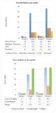
There was a marked difference in stresses produced in the maxilla and the mandible, among the groups. The maximum stresses of 28.1 MPa was seen in the glenoid fossa of Group 4 and the minimum stresses were noted in the maxillary tuberosity, ANS and premolar regions in Group 1. The stresses generated in Group 1 were overall lesser, compared to the other groups. The total overall stresses were maximum in Group 4.
Discussion
The reverse twin block addresses the problem of a Class III malocclusion in growing patients as an alternate to the FR3 or an upper removable appliance alone. Changes with reverse twin block were seen rapidly in 6.6 months compared to FR3 appliance that achieved similar results in 3.1 years [8]. In this context, morphological and biological changes of the mandible from reverse twin block forces have been investigated by means of cephalometric and experimental studies [8,34-37]. These studies revealed morphological changes of the maxilla and the mandible incident to reverse twin block appliance as follows, i.e., compensation was achieved with minimal skeletal changes. Correction is achieved by upper incisor proclination, while the mandible rotates slightly downwards and backwards to improve the skeletal relationship with increase of the ramus and gonial angle.
The occlusal forces are directed downward and backward on the mandibular teeth by the reversed incline planes. Due to the downward and forward position of condyle in the fossa, the bite is hinged open and no damaging force is exerted on the condyles. In the mandible, the force vector passes towards the gonial angle via the mandibular molars. The occlusal forces are best absorbed in this area of the mandible. The association between remodelling of the craniofacial bones with biomechanical components which is a key to any biological changes in the bony structures, has not been fully elucidated.
Biomechanical studies have revealed that stresses are the key to remodelling of the alveolar and craniofacial bones incident to functional and orthopaedic forces [38,39]. It is indicated that, for long bones, the mechanical strains from functional or dynamic forces play a role in altering the shape of bones [40,41]. Moreover, electrical charges created by mechanical stresses are shown to be linked to bone remodelling and the compressive stresses in the mandible and on the condyle, result in inhibition of interstitial growth of the mandible and condylar growth [42,43]. The mechanism of remodelling of the maxilla and mandible from reverse twin block forces may be derived from these findings. As per the association between bone remodelling and stresses, the following sequence can be postulated. Compressive and tensile stresses produce different electrical potentials, which further trigger osteoclasts and osteoblasts in the stressed areas. Then, remodelling of bones such as resorption and deposition will be induced by the cellular activity.
The results of the present study concur with those findings, as significant stresses were noted in the condylar region that presumably equates with condylar remodelling and also, stresses in the gonial region were observed. Clark W suggests construction of reverse twin block in maximum retrusive position and an interincisal clearance of 2 mm and 4 mm in mesofacial and brachyfacial types respectively [10]. However, the results of this study suggest that there is disparity in stresses and displacement with varying construction bite heights of 2 mm and 4 mm. This is in accordance to a study by Noro T et al., that a higher construction bite may produce more optimal changes of the craniofacial skeleton for the more horizontal direction of the forces, which is effective for repositioning of the mandible [14].
The major proprioceptive stimulus for growth is through the occlusal forces which results in remodelling of the alveolar trabecular system and periosteal and endochondral apposition to meet the necessities of occlusal function.
The results obtained in this study showed that maximum stresses were observed in the models with passive tension associated with bite force i.e., Group 2 and Group 4. Further, increasing the height of the construction bite, coupled with passive tension and bite force, yielded more stresses in the region of mandibular molars, the neck of the condyle, the gonial region, the glenoid fossa, ANS and maxillary tuberosity. Stresses at the molars were a result of the reverse twin block appliance in direct contact with the teeth and the force incident on the inclined planes being directed downward and backward on the mandible.
The resultant displacement, though dentoalveolar, was observed to be more in the maxilla than the mandible. The possible reason could be due to the angulation of the inclined planes that harness the occlusal forces that drive the upper teeth forward and at the same time the lower arch serves as a means of anchorage thereby restricting mandibular development, as suggested by Clark W [10]. Maximum stresses were seen at the condylar neck, this is coincident with the insertion of lateral pterygoid muscle at the neck of the condyle which is involved in the depressing of the mandible.
Limitation
The influence of the lateral pterygoid muscle on the TMJ and condylar remodelling is not under the scope of this study and paves way for future research.
Suggestions for future directions:
To study the effects of various construction bites at the histological and genetic level.
To study the role of lateral pterygoid in influencing the temporomandibular joint in detail.
Conclusion
The displacement resulting from reverse twin block was mainly dentoalveolar in nature with the maxillary incisors displacement more than the mandibular incisors in addition to the downward and forward displacement of mandible.
In the mandible, the maximum Von Mises stress was recorded in the region of condylar process for Group 4 with 4 mm of interincisal clearance with passive tension and maximum bite force and the minimum Von Mises stress was recorded in the gonial region for Group 1 with 2 mm of interincisal clearance with passive tension.
In the maxilla, the maximum Von Mises stress was recorded in the region of glenoid fossa for Group 4 with 4 mm of interincisal clearance with passive tension and maximum bite force and the minimum Von Mises stress was recorded in cervical aspect of upper teeth for Group 1 with 2 mm of interincisal clearance with passive tension.
[1]. Hamamcı N, Başaran G, Şahin S, Nonsurgical correction of an adult skeletal Class III and open-bite malocclusionThe Angle Orthod 2006 76(3):527-32. [Google Scholar]
[2]. Lew KK, Foong WC, Loh E, Malocclusion prevalence in an ethnic Chinese populationAust Dent J 1993 38(6):442-49.10.1111/j.1834-7819.1993.tb04759.x8110079 [Google Scholar] [CrossRef] [PubMed]
[3]. Ishii H, Morita S, Takeuchi Y, Nakamura S, Treatment effect of combined maxillary protraction and chincap appliance in severe skeletal Class III casesAm J Orthod Dentofac 1987 92(4):304-12.10.1016/0889-5406(87)90331-3 [Google Scholar] [CrossRef]
[4]. Thilander B, Myrberg N, The prevalence of malocclusion in Swedish school childrenEur J Oral Sci 1973 81(1):12-20.10.1111/j.1600-0722.1973.tb01489.x4510864 [Google Scholar] [CrossRef] [PubMed]
[5]. Tschill P, Bacon W, Sonko A, Malocclusion in the deciduous dentition of Caucasian childrenEur J Orthodont 1997 19(4):361-67.10.1093/ejo/19.4.3619308256 [Google Scholar] [CrossRef] [PubMed]
[6]. Newman GV, Prevalence of malocclusion in children six to fourteen years of age and treatment in preventable casesJ Am Dent Assoc 1956 52(5):566-75.10.14219/jada.archive.1956.009213353914 [Google Scholar] [CrossRef] [PubMed]
[7]. Gencer D, Kaygisiz E, Yüksel S, Tortop T, Comparison of double-plate appliance/facemask combination and facemask therapy in treating Class III malocclusionsThe Angle Orthod 2014 85(2):278-83.10.2319/013114-83.124913739 [Google Scholar] [CrossRef] [PubMed]
[8]. Kinder G, DiBiase A, DiBiase D, Class III Twin Blocks: a case seriesJ Orthod 2003 30(3):197-201.10.1093/ortho/30.3.19714530416 [Google Scholar] [CrossRef] [PubMed]
[9]. Frankel R, Maxillary retrusion in Class 3 and treatment with the function corrector 3Trans Eur Orthod Soc 1970 :249-59. [Google Scholar]
[10]. Clark W, Twin block functional therapy 2014 JP Medical Ltd10.5005/jp/books/12534_18PMC4708102 [Google Scholar] [CrossRef] [PubMed]
[11]. Parle D, Desai D, Bansal A, Estimation of individual bite force during normal occlusion using feaIn Proceedings of the Altair Technology Conference, Pune, India 2013 :18-19. [Google Scholar]
[12]. Andresen V, Haupl K, Functional orthodonticsThe basics of the Norwegian system 1936 LeipzigH. Meusser[translated from: German] [Google Scholar]
[13]. Woodside DG, Some effects of activator treatment on the growth rate of the mandible and position of the midfaceInTransactions of Third International Orthodontic Congress 1973 The CV Mosby Company [Google Scholar]
[14]. Noro T, Tanne K, Sakuda M, Orthodontic forces exerted by activators with varying construction bite heightsAm J Orthod Dentofac 1994 105(2):169-79.10.1016/S0889-5406(94)70113-X [Google Scholar] [CrossRef]
[15]. de Alba JA, Chaconas SJ, Caputo AA, Emison W, Stress distribution under high-pull extraoral chin cup traction: a photoelastic studyThe Angle Orthod 1982 52(1):69-78. [Google Scholar]
[16]. Ichikawa K, Nakagaw M, Kamogashira K, Hata S, Itoh T, Matsumoto M, The effect of orthopedic forces on the craniofacial complex using maxillary protraction-strain gage measurementsNihon Kyōsei Shika Gakkai zasshi 1984 43(3):325 [Google Scholar]
[17]. Toh T, Chaconas SJ, Caputo AA, Matyas J, Photoelastic effects of maxillary protraction on the craniofacial complexAm J Orthod 1985 88(2):117-24.10.1016/0002-9416(85)90235-0 [Google Scholar] [CrossRef]
[18]. Ijima M, Action patterns of orthopedic forces on the maxillary complex utilizing holography interference and strain gauge methodsNihon Kyosei Shika Gakkai zasshi 1988 47(1):127-44. [Google Scholar]
[19]. Thresher RW, Saito GE, The stress analysis of human teethJ Biomech 1973 6(5):443-49.10.1016/0021-9290(73)90003-1 [Google Scholar] [CrossRef]
[20]. Farah JW, Craig RG, Sikarskie DL, Photoelastic and finite element stress analysis of a restored axisymmetric first molarJ Biomech 1973 6(5):511IN9515-4520.10.1016/0021-9290(73)90009-2 [Google Scholar] [CrossRef]
[21]. Chaudhry A, Sidhu MS, Chaudhary G, Grover S, Chaudhry N, Kaushik A, Evaluation of stress changes in the mandible with a fixed functional appliance: A finite element studyAm J Orthod Dentofac 2015 147(2):226-34.10.1016/j.ajodo.2014.09.02025636557 [Google Scholar] [CrossRef] [PubMed]
[22]. Chaconas SJ, Caputo AA, Davis JC, The effects of orthopedic forces on the craniofacial complex utilizing cervical and headgear appliancesAm J Orthod 1976 69(5):527-39.10.1016/S0002-9416(76)80026-7 [Google Scholar] [CrossRef]
[23]. Chugh VK, Tandon P, Prasad V, Chugh A, Early orthopedic correction of skeletal Class III malocclusion using combined reverse twin block and face mask therapyJ Indian Soc Pedod Prev Dent 2015 33(1):310.4103/0970-4388.14896025572365 [Google Scholar] [CrossRef] [PubMed]
[24]. Cozza P, Baccetti T, Mucedero M, Pavoni C, Franchi L, Treatment and posttreatment effects of a facial mask combined with a bite-block appliance in Class III malocclusionAm J Orthod Dentofac 2010 138(3):300-10.10.1016/j.ajodo.2010.05.00120816299 [Google Scholar] [CrossRef] [PubMed]
[25]. Garattini G, Levrini L, Crozzoli P, Levrini A, Skeletal and dental modifications produced by the Bionator III applianceAm J Orthod Dentofac 1998 114(1):40-44.10.1016/S0889-5406(98)70235-5 [Google Scholar] [CrossRef]
[26]. Kilic N, Celikoglu M, Oktay H, Effects of the functional regulator III on transversal changes: a postero-anterior cephalometric and model studyEur J Orthod 2010 33(6):727-31.10.1093/ejo/cjq14021062966 [Google Scholar] [CrossRef] [PubMed]
[27]. Gupta A, Kohli VS, Hazarey PV, Kharbanda OP, Gunjal A, Stress distribution in the temporomandibular joint after mandibular protraction: a 3-dimensional finite element method study. Part 1Am J Orthod Dentofac 2009 135(6):737-48.10.1016/j.ajodo.2007.12.02519524833 [Google Scholar] [CrossRef] [PubMed]
[28]. Miyasaka-Hiraga J, Tanne K, Nakamura S, Finite element analysis for stresses in the craniofacial sutures produced by maxillary protraction forces applied at the upper caninesBr J Orthod 1994 21(4):343-48.10.1179/bjo.21.4.3437857893 [Google Scholar] [CrossRef] [PubMed]
[29]. Hypermesh A, Altair Hypermesh Manual 2000 USAAltair Inc.https://altairhyperworks.com/product/HyperMesh [Google Scholar]
[30]. Tanne K, Yoshida S, Kawata T, Sasaki A, Knox J, Jones ML, An evaluation of the biomechanical response of the tooth and periodontium to orthodontic forces in adolescent and adult subjectsJ Orthod 1998 25(2):109-15.10.1093/ortho/25.2.1099668993 [Google Scholar] [CrossRef] [PubMed]
[31]. Kim HS, Lee YK, Park JY, Development of FEA procedures for mechanical behaviors of maxilla, teeth and mandibleInt J of Precis Eng and Manuf 2016 17(6):785-92.10.1007/s12541-016-0096-7 [Google Scholar] [CrossRef]
[32]. Cattaneo PM, Dalstra M, Melsen B, The finite element method: a tool to study orthodontic tooth movementJ. Dent. Res 2005 84(5):428-33.10.1177/15440591050840050615840778 [Google Scholar] [CrossRef] [PubMed]
[33]. Borie E, Orsi IA, Noritomi PY, Kemmoku DT, Borie E, Orsi I, Noritomi P, Kemmoku D, Total Deformation of Multiple Implant-Supported Prostheses through Three-Dimensional Finite Element AnalysisInt. j. odontostomatol. (Print) 2015 9(3):437-42.10.4067/S0718-381X2015000300013 [Google Scholar] [CrossRef]
[34]. Sargod SS, Shetty N, Shabbir A, Early class III management in deciduous dentition using reverse twin blockJ Indian Soc Pedod Prev Dent 2013 31(1):5610.4103/0970-4388.11241823727746 [Google Scholar] [CrossRef] [PubMed]
[35]. Seehra J, Fleming PS, Mandall N, Dibiase AT, A comparison of two different techniques for early correction of Class III malocclusionThe Angle Orthod 2011 82(1):96-101.10.2319/032011-197.121806467 [Google Scholar] [CrossRef] [PubMed]
[36]. Verma G, Nagar A, Tandon P, Verma SL, Management of developing Class III malocclusionIndian J Oral Sci 2014 5(3):13410.4103/0976-6944.144533 [Google Scholar] [CrossRef]
[37]. Mittal M, Singh H, Kumar A, Sharma P, Reverse twin block for interceptive management of developing Class III malocclusionJ Indian Soc Pedod Prev Dent 2017 35(1):8610.4103/0970-4388.19922128139489 [Google Scholar] [CrossRef] [PubMed]
[38]. Tanne K, Lu YC, Tanaka E, Sakuda M, Biomechanical changes of the mandible from orthopaedic chin cup force studied in a three-dimensional finite element modelEur J Orthod 1993 15(6):527-33.10.1093/ejo/15.6.5278112419 [Google Scholar] [CrossRef] [PubMed]
[39]. Tanne K, Sakuda M, Biomechanical and clinical changes of the craniofacial complex from orthopedic maxillary protractionThe Angle Orthod 1991 61(2):145-52. [Google Scholar]
[40]. Churches AE, Howlett CR, Waldron KJ, Ward GW, The response of living bone to controlled time-varying loading: method and preliminary resultsJ Biomech 1979 12(1):35-45.10.1016/0021-9290(79)90007-1 [Google Scholar] [CrossRef]
[41]. Lanyon LE, Rubin CT, Static vs dynamic loads as an influence on bone remodellingJ Biomech 1984 17(12):897-905.10.1016/0021-9290(84)90003-4 [Google Scholar] [CrossRef]
[42]. Cochran GV, Pawluk RJ, Bassett CA, Stress generated electric potentials in the mandible and teethArch. Oral Biol 1967 12(7):917IN25-20.10.1016/0003-9969(67)90117-3 [Google Scholar] [CrossRef]
[43]. Gross D, Williams WS, Streaming potential and the electromechanical response of physiologically-moist boneJ Biomech 1982 15(4):277-95.10.1016/0021-9290(82)90174-9 [Google Scholar] [CrossRef]